Isolator Function
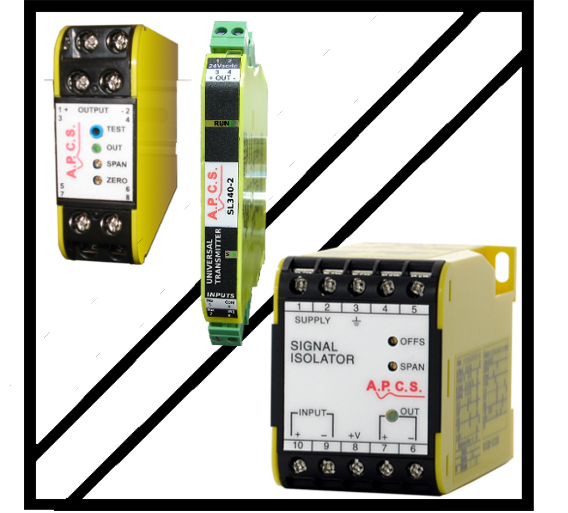
Select products that include an Isolation function.
Find Isolator select ⇒ Input ⇒ Output
- 4-20mA
- 4-20mA, Select Output
- 4-20mA 2-Wire
- 4-20mA 4-20mA 2-Wire, Select Product
- SI231 Signal Isolator
- SI239 Signal Isolator

- 4-20mA 4-Wire
- dc mA/V 3-Wire
- 4-20mA dc mA/V 3-Wire, Select Product
- SI231 Signal Isolator
- SI239 Signal Isolator

- dc mA/V 4-Wire
- Bipolar
- 4-20mA Bipolar, Select Product
- BSI234 Bipolar Signal Isolator
- BSI134 Bipolar Signal Isolator

- High Drive
- 4-20mA High Drive, Select Product
- BSI134 Bipolar Signal Isolator

- Pulse/ Frequency
- 4-20mA Pulse/ Frequency, Select Product
- APC258 Analogue to Pulse Converter
- PWM157 Analog To PWM

- Relay
- 4-20mA Relay, Select Product
- DTI135 Dual Trippoint Isolator
- STI136 Single Trippoint Isolator

- Resistance
- 4-20mA Resistance, Select Product
- ATR167 Analog To Resistance
- ATP168 Analog to Potentiometer


- 4-20mA Input Powered
- 4-20mA Input Powered, Select Output
- 4-20mA Input Powered
- 4-20mA Input Powered 4-20mA Input Powered, Select Product
- SPI232 Signal Powered Isolator


- ac A
- ac A, Select Output
- 4-20mA 2-Wire
- ac A 4-20mA 2-Wire, Select Product
- ACT241 ac Current Transducer

- 4-20mA 4-Wire
- dc mA/V 3-Wire
- ac A dc mA/V 3-Wire, Select Product
- ACT241 ac Current Transducer

- dc mA/V 4-Wire
- Pulse/ Frequency
- ac A Pulse/ Frequency, Select Product
- APC258 Analogue to Pulse Converter

- Relay
- ac A Relay, Select Product
- DTI135 Dual Trippoint Isolator
- STI136 Single Trippoint Isolator


- ac V
- ac V, Select Output
- 4-20mA 2-Wire
- ac V 4-20mA 2-Wire, Select Product
- SI239 Signal Isolator
- AVT245 ac Voltage Transducer

- 4-20mA 4-Wire
- dc mA/V 3-Wire
- ac V dc mA/V 3-Wire, Select Product
- SI239 Signal Isolator
- AVT245 ac Voltage Transducer

- dc mA/V 4-Wire
- Pulse/ Frequency
- ac V Pulse/ Frequency, Select Product
- APC258 Analogue to Pulse Converter

- Relay
- ac V Relay, Select Product
- DTI135 Dual Trippoint Isolator
- STI136 Single Trippoint Isolator


- Conductivity
- Conductivity, Select Output
- 4-20mA 2-Wire
- Conductivity 4-20mA 2-Wire, Select Product
- CDT228 Conductivity Transmitter

- 4-20mA 4-Wire
- Conductivity 4-20mA 4-Wire, Select Product
- CDT128 Conductivity Transmitter

- dc mA/V 3-Wire
- Conductivity dc mA/V 3-Wire, Select Product
- CDT228 Conductivity Transmitter

- dc mA/V 4-Wire
- Conductivity dc mA/V 4-Wire, Select Product
- CDT128 Conductivity Transmitter


- Connector
- Connector, Select Output
- 4-20mA 4-Wire
- Connector 4-20mA 4-Wire, Select Product
- SL303 SL Series USB Isolator


- dc A
- dc A, Select Output
- 4-20mA 4-Wire
- dc A 4-20mA 4-Wire, Select Product
- SL345 AC and Bipolar Isolator
- DCT247 Dc Current Transducer
- SI139 Signal Isolator

- dc mA/V 4-Wire
- dc A dc mA/V 4-Wire, Select Product
- SL345 AC and Bipolar Isolator
- DCT247 Dc Current Transducer
- SI139 Signal Isolator

- Pulse/ Frequency
- dc A Pulse/ Frequency, Select Product
- APC258 Analogue to Pulse Converter


- dc mA/V
- dc mA/V, Select Output
- 4-20mA 2-Wire
- dc mA/V 4-20mA 2-Wire, Select Product
- SI231 Signal Isolator
- SI239 Signal Isolator

- 4-20mA 4-Wire
- dc mA/V 3-Wire
- dc mA/V dc mA/V 3-Wire, Select Product
- SI231 Signal Isolator
- SI239 Signal Isolator

- dc mA/V 4-Wire
- Bipolar
- dc mA/V Bipolar, Select Product
- BSI234 Bipolar Signal Isolator
- BSI134 Bipolar Signal Isolator

- High Drive
- dc mA/V High Drive, Select Product
- BSI134 Bipolar Signal Isolator

- Pulse/ Frequency
- dc mA/V Pulse/ Frequency, Select Product
- APC258 Analogue to Pulse Converter
- PWM157 Analog To PWM

- Relay
- dc mA/V Relay, Select Product
- DTI135 Dual Trippoint Isolator
- STI136 Single Trippoint Isolator

- Resistance
- dc mA/V Resistance, Select Product
- ATR167 Analog To Resistance
- ATP168 Analog to Potentiometer


- mV
- mV, Select Output
- 4-20mA 2-Wire
- mV 4-20mA 2-Wire, Select Product
- MVT223 Millivolt Transmitter
- SI239 Signal Isolator

- 4-20mA 4-Wire
- mV 4-20mA 4-Wire, Select Product
- SL340 Universal Transmitter
- SSP235 Signal Splitter
- DTI135 Dual Trippoint Isolator
- STI136 Single Trippoint Isolator
- SI139 Signal Isolator

- dc mA/V 3-Wire
- mV dc mA/V 3-Wire, Select Product
- MVT223 Millivolt Transmitter
- SI239 Signal Isolator

- dc mA/V 4-Wire
- mV dc mA/V 4-Wire, Select Product
- SL340 Universal Transmitter
- SSP235 Signal Splitter
- DTI135 Dual Trippoint Isolator
- STI136 Single Trippoint Isolator
- SI139 Signal Isolator

- Bipolar
- mV Bipolar, Select Product
- BSI234 Bipolar Signal Isolator

- Pulse/ Frequency
- mV Pulse/ Frequency, Select Product
- APC258 Analogue to Pulse Converter

- Relay
- mV Relay, Select Product
- DTI135 Dual Trippoint Isolator
- STI136 Single Trippoint Isolator


- pH/REDOX
- pH/REDOX, Select Output
- 4-20mA 2-Wire
- pH/REDOX 4-20mA 2-Wire, Select Product
- PHT229 pH / Redox Transmitter

- 4-20mA 4-Wire
- pH/REDOX 4-20mA 4-Wire, Select Product
- PHT129 pH / Redox Transmitter

- dc mA/V 3-Wire
- pH/REDOX dc mA/V 3-Wire, Select Product
- PHT229 pH / Redox Transmitter

- dc mA/V 4-Wire
- pH/REDOX dc mA/V 4-Wire, Select Product
- PHT129 pH / Redox Transmitter

- Pulse/ Frequency
- pH/REDOX Pulse/ Frequency, Select Product
- APC258 Analogue to Pulse Converter


- Position
- Position, Select Output
- 4-20mA 4-Wire
- Position 4-20mA 4-Wire, Select Product
- TPT194 Tap Position Transducer

- dc mA/V 4-Wire
- Position dc mA/V 4-Wire, Select Product
- TPT194 Tap Position Transducer


- Potentiometer
- Potentiometer, Select Output
- 4-20mA 4-Wire
- Potentiometer 4-20mA 4-Wire, Select Product
- SL340 Universal Transmitter
- DTI135 Dual Trippoint Isolator
- STI136 Single Trippoint Isolator
- SI139 Signal Isolator

- dc mA/V 4-Wire
- Potentiometer dc mA/V 4-Wire, Select Product
- SL340 Universal Transmitter
- DTI135 Dual Trippoint Isolator
- STI136 Single Trippoint Isolator
- SI139 Signal Isolator

- Bipolar
- Potentiometer Bipolar, Select Product
- BSI234 Bipolar Signal Isolator
- BSI134 Bipolar Signal Isolator

- High Drive
- Potentiometer High Drive, Select Product
- BSI134 Bipolar Signal Isolator

- Pulse/ Frequency
- Potentiometer Pulse/ Frequency, Select Product
- APC258 Analogue to Pulse Converter

- Relay
- Potentiometer Relay, Select Product
- DTI135 Dual Trippoint Isolator
- STI136 Single Trippoint Isolator

- Resistance
- Potentiometer Resistance, Select Product
- ATR167 Analog To Resistance
- ATP168 Analog to Potentiometer


- Resistance
- Resistance, Select Output
- 4-20mA 2-Wire
- Resistance 4-20mA 2-Wire, Select Product
- RT243 Resistance Transmitter

- 4-20mA 4-Wire
- Resistance 4-20mA 4-Wire, Select Product
- SL340 Universal Transmitter
- DTI135 Dual Trippoint Isolator
- STI136 Single Trippoint Isolator

- dc mA/V 3-Wire
- Resistance dc mA/V 3-Wire, Select Product
- RT243 Resistance Transmitter

- dc mA/V 4-Wire
- Resistance dc mA/V 4-Wire, Select Product
- SL340 Universal Transmitter
- DTI135 Dual Trippoint Isolator
- STI136 Single Trippoint Isolator

- Pulse/ Frequency
- Resistance Pulse/ Frequency, Select Product
- APC258 Analogue to Pulse Converter

- Relay
- Resistance Relay, Select Product
- DTI135 Dual Trippoint Isolator
- STI136 Single Trippoint Isolator

- Resistance
- Resistance Resistance, Select Product
- ATR167 Analog To Resistance
- ATP168 Analog to Potentiometer


- RTD
- RTD, Select Output
- 4-20mA 2-Wire
- RTD 4-20mA 2-Wire, Select Product
- RTDT225 RTD Temperature Transmitter

- 4-20mA 4-Wire
- RTD 4-20mA 4-Wire, Select Product
- SL340 Universal Transmitter
- DTI135 Dual Trippoint Isolator
- STI136 Single Trippoint Isolator

- dc mA/V 3-Wire
- RTD dc mA/V 3-Wire, Select Product
- RTDT225 RTD Temperature Transmitter

- dc mA/V 4-Wire
- RTD dc mA/V 4-Wire, Select Product
- SL340 Universal Transmitter
- DTI135 Dual Trippoint Isolator
- STI136 Single Trippoint Isolator

- Pulse/ Frequency
- RTD Pulse/ Frequency, Select Product
- APC258 Analogue to Pulse Converter

- Relay
- RTD Relay, Select Product
- DTI135 Dual Trippoint Isolator
- STI136 Single Trippoint Isolator

- Resistance
- RTD Resistance, Select Product
- ATR167 Analog To Resistance
- ATP168 Analog to Potentiometer


- Signal Powered
- Signal Powered, Select Output
- 4-20mA 4-Wire
- Signal Powered 4-20mA 4-Wire, Select Product
- STI136 Single Trippoint Isolator

- dc mA/V 4-Wire
- Signal Powered dc mA/V 4-Wire, Select Product
- STI136 Single Trippoint Isolator

- Relay
- Signal Powered Relay, Select Product
- STI136 Single Trippoint Isolator


- Speed/ Frequency/ Pulse
- Speed/ Frequency/ Pulse, Select Output
- 4-20mA 2-Wire
- Speed/ Frequency/ Pulse 4-20mA 2-Wire, Select Product
- FRT250 Frequency Transmitter

- 4-20mA 4-Wire
- Speed/ Frequency/ Pulse 4-20mA 4-Wire, Select Product
- SL350 Pulse Frequency Transmitter
- DTI135 Dual Trippoint Isolator
- STI136 Single Trippoint Isolator

- dc mA/V 3-Wire
- Speed/ Frequency/ Pulse dc mA/V 3-Wire, Select Product
- FRT250 Frequency Transmitter

- dc mA/V 4-Wire
- Speed/ Frequency/ Pulse dc mA/V 4-Wire, Select Product
- SL350 Pulse Frequency Transmitter
- DTI135 Dual Trippoint Isolator
- STI136 Single Trippoint Isolator

- Pulse/ Frequency
- Speed/ Frequency/ Pulse Pulse/ Frequency, Select Product
- PLS257 Pulse Splitter
- APC258 Analogue to Pulse Converter

- Relay
- Speed/ Frequency/ Pulse Relay, Select Product
- DTI135 Dual Trippoint Isolator
- STI136 Single Trippoint Isolator

- Resistance
- Speed/ Frequency/ Pulse Resistance, Select Product
- ATR167 Analog To Resistance
- ATP168 Analog to Potentiometer


- Strain Gauge
- Strain Gauge, Select Output
- 4-20mA 2-Wire
- Strain Gauge 4-20mA 2-Wire, Select Product
- WT227 Strain Gauge Transmitter

- 4-20mA 4-Wire
- Strain Gauge 4-20mA 4-Wire, Select Product
- SL340 Universal Transmitter
- WT127 Strain Gauge Transmitter

- dc mA/V 3-Wire
- Strain Gauge dc mA/V 3-Wire, Select Product
- WT227 Strain Gauge Transmitter

- dc mA/V 4-Wire
- Strain Gauge dc mA/V 4-Wire, Select Product
- SL340 Universal Transmitter
- WT127 Strain Gauge Transmitter


- Thermocouple
- Thermocouple, Select Output
- 4-20mA 2-Wire
- Thermocouple 4-20mA 2-Wire, Select Product
- TCT226 Thermocouple Transmitter

- 4-20mA 4-Wire
- Thermocouple 4-20mA 4-Wire, Select Product
- SL340 Universal Transmitter
- DTI135 Dual Trippoint Isolator
- STI136 Single Trippoint Isolator
- TCT286 Thermocouple Transmitter/Isolator

- dc mA/V 3-Wire
- Thermocouple dc mA/V 3-Wire, Select Product
- TCT226 Thermocouple Transmitter

- dc mA/V 4-Wire
- Thermocouple dc mA/V 4-Wire, Select Product
- SL340 Universal Transmitter
- DTI135 Dual Trippoint Isolator
- STI136 Single Trippoint Isolator
- TCT286 Thermocouple Transmitter/Isolator

- Relay
- Thermocouple Relay, Select Product
- DTI135 Dual Trippoint Isolator
- STI136 Single Trippoint Isolator

- Resistance
- Thermocouple Resistance, Select Product
- ATR167 Analog To Resistance
- ATP168 Analog to Potentiometer


- Select an Input (above)

Select products that include an Isolation function.

Isolator Function
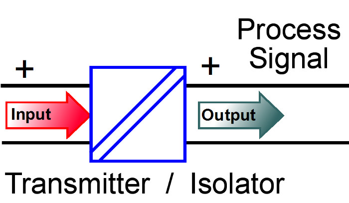
A Signal Isolator is a Signal transmitter with Isolation
Isolation is the electrical separation of two circuits such that there is no electron flow between the two circuits.
Signal Isolation
Isolation is one of the most critical issues in process control. It is used to prevent unwanted current loops, ground loops, protection of delicate equipment and ensuring the safety of human operators when high common mode voltages are to be expected.
Isolation is the electrical separation of two circuits such that there is no electron flow between the two circuits. The isolation breakdown voltage defined for such equipment, is the voltage required to cause flash-over or a breakdown in isolation, in such a circuit.
Isolation in general purpose analogue circuits is usually achieved by passing signal over a barrier using magnetic or optical coupling then converting the signal to the required output type.
There are usually three isolation paths to be considered; supply to input, supply to output and input to output.
- Signal powered isolators provide isolation for the input / output and output / supply paths, but not for the input / supply path (as the signal is the supply).
- Loop powered isolators provide isolation for the input / output and input / supply paths, but not for the output / supply path.
- Only a 4-wire or separately powered transmitter will provide true 3-way galvanic isolation will isolate all three paths.
The need for Isolation
In most processes there are pieces of electronic measurement and control equipment from many different manufactures. The signals from these instruments are interconnected to each other and to sensors, transducers and output devices connected in the process loop. In any such measurement and control system there are several problems that are likely to occur, all of which can be solved by incorporating the appropriate isolation between signals.
Proper isolation should be of the highest priority in process control systems. Used correctly isolation will prevent unwanted current loops, ground loops, damage to delicate equipment and ensure the safety of human operators when high common mode voltages are to be expected.
Common Ground Loop Problems
This type of fault occurs when the return path of least resistance for the signal is via the earth or ground. An example of this type of fault is when measuring the pH of a liquid and the liquid has a return path to a grounded power supply.
It must be remembered that if the measurement is not isolated the return path could be through any one of the instruments connected to the same plant.
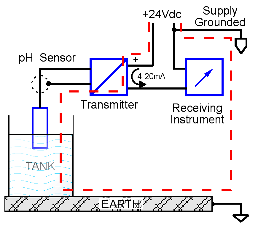
Common Ground Loop Problem
Common Current Loops Problems
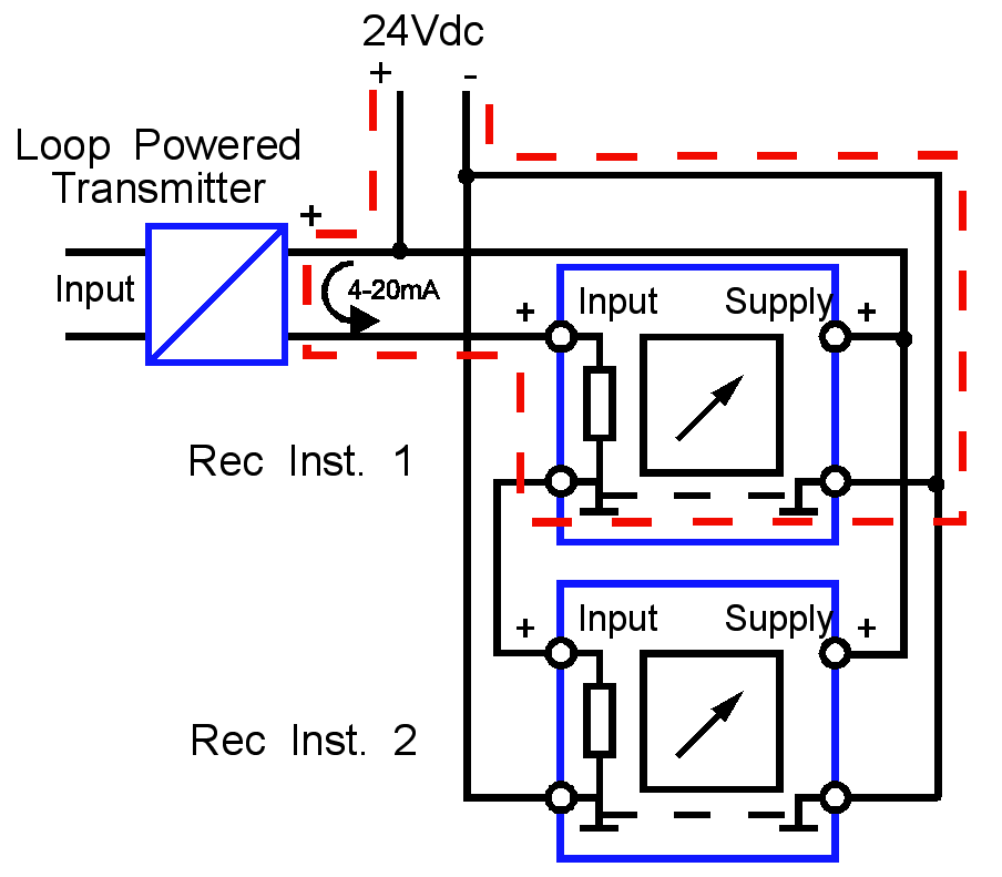
Common Current Loop Problem
A current looping problem will arise whenever the path of least resistance for the output loop current is not the intended path.
A classic example of this is shown below, the two receiving instruments are supplied from the same 24Vdc supply and have a common input and supply negative.
In this illustration the current flows into Rec Inst. 1 where it finds the path of least resistance to return to the supply ground is return via the Rec Inst. 1 negative supply rail, thus bypassing the input of Rec Inst. 2.
Common Floating Voltage Problems
Dangerous high voltages can be present at sensor level, as in the case with a dc shunt. This voltage will be conducted through a non-isolated transmitter creating a threat to humans with a floating load or damage to receiving devices.
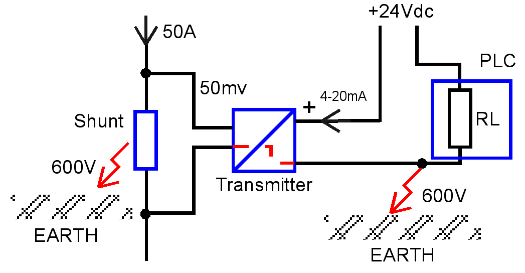
Common Floating Voltage Problem
Common Mode Noise
Often the signals from sensors and transducers are small voltages and susceptible to noise pick-up from motors, variable speed drives and general switching spikes carried by the electrical reticulation system.
If there is isolation between input and output, the common mode noise (present on both input terminals with reference to ground) will be prevented from passing to the output even if it is relatively high in magnitude.