dc Input Conditioning

Select products that measure dc input parameters and produce a standard process signal output or an alarm state.
Find a Product Input ⇒ Function ⇒ Output
- 4-20mA
- 4-20mA, Select Function
- Alarm
- 4-20mA Alarm, Select Output
- 4-20mA 4-Wire
- 4-20mA Alarm 4-20mA 4-Wire, Select Product
- DTI135 Dual Trippoint Isolator
- STI136 Single Trippoint Isolator

- dc mA/V 4-Wire
- 4-20mA Alarm dc mA/V 4-Wire, Select Product
- DTI135 Dual Trippoint Isolator
- STI136 Single Trippoint Isolator

- Relay
- 4-20mA Alarm Relay, Select Product
- DTA137 Dual Trip Alarm
- STA138 Single Trip Alarm
- TRA173 Triple Trip Alarm
- DTI135 Dual Trippoint Isolator
- STI136 Single Trippoint Isolator


- Isolator
- 4-20mA Isolator, Select Output
- 4-20mA 2-Wire
- 4-20mA Isolator 4-20mA 2-Wire, Select Product
- SI231 Signal Isolator
- SI239 Signal Isolator

- 4-20mA 4-Wire
- 4-20mA Isolator 4-20mA 4-Wire, Select Product
- SL332 Signal Isolator
- SL335 Signal Splitter
- SL339 Signal Isolator
- SSP235 Signal Splitter
- HVI237 5KV Isolator
- DTI135 Dual Trippoint Isolator
- STI136 Single Trippoint Isolator
- SI139 Signal Isolator

- dc mA/V 3-Wire
- 4-20mA Isolator dc mA/V 3-Wire, Select Product
- SI231 Signal Isolator
- SI239 Signal Isolator

- dc mA/V 4-Wire
- 4-20mA Isolator dc mA/V 4-Wire, Select Product
- SL332 Signal Isolator
- SL335 Signal Splitter
- SL339 Signal Isolator
- SSP235 Signal Splitter
- HVI237 5KV Isolator
- DTI135 Dual Trippoint Isolator
- STI136 Single Trippoint Isolator
- SI139 Signal Isolator

- Bipolar
- 4-20mA Isolator Bipolar, Select Product
- BSI234 Bipolar Signal Isolator
- BSI134 Bipolar Signal Isolator

- High Drive
- 4-20mA Isolator High Drive, Select Product
- BSI134 Bipolar Signal Isolator

- Pulse/ Frequency
- 4-20mA Isolator Pulse/ Frequency, Select Product
- APC258 Analogue to Pulse Converter
- PWM157 Analog To PWM

- Relay
- 4-20mA Isolator Relay, Select Product
- DTI135 Dual Trippoint Isolator
- STI136 Single Trippoint Isolator

- Resistance
- 4-20mA Isolator Resistance, Select Product
- ATR167 Analog To Resistance
- ATP168 Analog to Potentiometer


- Transmitter
- 4-20mA Transmitter, Select Output
- 4-20mA 2-Wire
- 4-20mA Transmitter 4-20mA 2-Wire, Select Product
- SI231 Signal Isolator
- SI239 Signal Isolator

- 4-20mA 4-Wire
- 4-20mA Transmitter 4-20mA 4-Wire, Select Product
- SL332 Signal Isolator
- SL335 Signal Splitter
- SL339 Signal Isolator
- SSP235 Signal Splitter
- HVI237 5KV Isolator
- DTI135 Dual Trippoint Isolator
- STI136 Single Trippoint Isolator
- SI139 Signal Isolator

- dc mA/V 3-Wire
- 4-20mA Transmitter dc mA/V 3-Wire, Select Product
- SI231 Signal Isolator
- SI239 Signal Isolator

- dc mA/V 4-Wire
- 4-20mA Transmitter dc mA/V 4-Wire, Select Product
- SL332 Signal Isolator
- SL335 Signal Splitter
- SL339 Signal Isolator
- SSP235 Signal Splitter
- HVI237 5KV Isolator
- DTI135 Dual Trippoint Isolator
- STI136 Single Trippoint Isolator
- SI139 Signal Isolator

- Bipolar
- 4-20mA Transmitter Bipolar, Select Product
- BSI234 Bipolar Signal Isolator
- BSC133 Bipolar Signal Converter
- BSI134 Bipolar Signal Isolator

- High Drive
- 4-20mA Transmitter High Drive, Select Product
- BSC133 Bipolar Signal Converter
- BSI134 Bipolar Signal Isolator
- PD121 Power Driver
- PD122 Power Driver

- Pulse/ Frequency
- 4-20mA Transmitter Pulse/ Frequency, Select Product
- APC258 Analogue to Pulse Converter
- PWM157 Analog To PWM

- Relay
- 4-20mA Transmitter Relay, Select Product
- DTI135 Dual Trippoint Isolator
- STI136 Single Trippoint Isolator

- Resistance
- 4-20mA Transmitter Resistance, Select Product
- ATR167 Analog To Resistance
- ATP168 Analog to Potentiometer


- 4-20mA Input Powered
- 4-20mA Input Powered, Select Function
- Isolator
- 4-20mA Input Powered Isolator, Select Output
- 4-20mA Input Powered
- 4-20mA Input Powered Isolator 4-20mA Input Powered, Select Product
- SPI232 Signal Powered Isolator


- dc A
- dc A, Select Function
- ac Transducer
- dc A ac Transducer, Select Output
- 4-20mA 4-Wire
- dc A ac Transducer 4-20mA 4-Wire, Select Product
- SL345 AC and Bipolar Isolator
- DCT247 Dc Current Transducer

- dc mA/V 4-Wire
- dc A ac Transducer dc mA/V 4-Wire, Select Product
- SL345 AC and Bipolar Isolator
- DCT247 Dc Current Transducer


- Alarm
- dc A Alarm, Select Output
- Relay
- dc A Alarm Relay, Select Product
- DCA218 dc Current Alarm


- Isolator
- dc A Isolator, Select Output
- 4-20mA 4-Wire
- dc A Isolator 4-20mA 4-Wire, Select Product
- SL345 AC and Bipolar Isolator
- DCT247 Dc Current Transducer
- SI139 Signal Isolator

- dc mA/V 4-Wire
- dc A Isolator dc mA/V 4-Wire, Select Product
- SL345 AC and Bipolar Isolator
- DCT247 Dc Current Transducer
- SI139 Signal Isolator

- Pulse/ Frequency
- dc A Isolator Pulse/ Frequency, Select Product
- APC258 Analogue to Pulse Converter


- Transmitter
- dc A Transmitter, Select Output
- 4-20mA 4-Wire
- dc A Transmitter 4-20mA 4-Wire, Select Product
- SL345 AC and Bipolar Isolator
- DCT247 Dc Current Transducer
- SI139 Signal Isolator

- dc mA/V 4-Wire
- dc A Transmitter dc mA/V 4-Wire, Select Product
- SL345 AC and Bipolar Isolator
- DCT247 Dc Current Transducer
- SI139 Signal Isolator

- Pulse/ Frequency
- dc A Transmitter Pulse/ Frequency, Select Product
- APC258 Analogue to Pulse Converter


- dc mA/V
- dc mA/V, Select Function
- ac Transducer
- dc mA/V ac Transducer, Select Output
- 4-20mA 4-Wire
- dc mA/V ac Transducer 4-20mA 4-Wire, Select Product
- SL345 AC and Bipolar Isolator

- dc mA/V 4-Wire
- dc mA/V ac Transducer dc mA/V 4-Wire, Select Product
- SL345 AC and Bipolar Isolator


- Alarm
- dc mA/V Alarm, Select Output
- 4-20mA 4-Wire
- dc mA/V Alarm 4-20mA 4-Wire, Select Product
- DTI135 Dual Trippoint Isolator
- STI136 Single Trippoint Isolator

- dc mA/V 4-Wire
- dc mA/V Alarm dc mA/V 4-Wire, Select Product
- DTI135 Dual Trippoint Isolator
- STI136 Single Trippoint Isolator

- Relay
- dc mA/V Alarm Relay, Select Product
- DTA137 Dual Trip Alarm
- STA138 Single Trip Alarm
- TRA173 Triple Trip Alarm
- DTI135 Dual Trippoint Isolator
- STI136 Single Trippoint Isolator


- Isolator
- dc mA/V Isolator, Select Output
- 4-20mA 2-Wire
- dc mA/V Isolator 4-20mA 2-Wire, Select Product
- SI231 Signal Isolator
- SI239 Signal Isolator

- 4-20mA 4-Wire
- dc mA/V Isolator 4-20mA 4-Wire, Select Product
- SL332 Signal Isolator
- SL335 Signal Splitter
- SL339 Signal Isolator
- SL345 AC and Bipolar Isolator
- SSP235 Signal Splitter
- HVI237 5KV Isolator
- DTI135 Dual Trippoint Isolator
- STI136 Single Trippoint Isolator
- SI139 Signal Isolator

- dc mA/V 3-Wire
- dc mA/V Isolator dc mA/V 3-Wire, Select Product
- SI231 Signal Isolator
- SI239 Signal Isolator

- dc mA/V 4-Wire
- dc mA/V Isolator dc mA/V 4-Wire, Select Product
- SL332 Signal Isolator
- SL335 Signal Splitter
- SL339 Signal Isolator
- SL345 AC and Bipolar Isolator
- SSP235 Signal Splitter
- HVI237 5KV Isolator
- DTI135 Dual Trippoint Isolator
- STI136 Single Trippoint Isolator
- SI139 Signal Isolator

- Bipolar
- dc mA/V Isolator Bipolar, Select Product
- BSI234 Bipolar Signal Isolator
- BSI134 Bipolar Signal Isolator

- High Drive
- dc mA/V Isolator High Drive, Select Product
- BSI134 Bipolar Signal Isolator

- Pulse/ Frequency
- dc mA/V Isolator Pulse/ Frequency, Select Product
- APC258 Analogue to Pulse Converter
- PWM157 Analog To PWM

- Relay
- dc mA/V Isolator Relay, Select Product
- DTI135 Dual Trippoint Isolator
- STI136 Single Trippoint Isolator

- Resistance
- dc mA/V Isolator Resistance, Select Product
- ATR167 Analog To Resistance
- ATP168 Analog to Potentiometer


- Transmitter
- dc mA/V Transmitter, Select Output
- 4-20mA 2-Wire
- dc mA/V Transmitter 4-20mA 2-Wire, Select Product
- SI231 Signal Isolator
- SI239 Signal Isolator

- 4-20mA 4-Wire
- dc mA/V Transmitter 4-20mA 4-Wire, Select Product
- SL332 Signal Isolator
- SL335 Signal Splitter
- SL339 Signal Isolator
- SL345 AC and Bipolar Isolator
- SSP235 Signal Splitter
- HVI237 5KV Isolator
- DTI135 Dual Trippoint Isolator
- STI136 Single Trippoint Isolator
- SI139 Signal Isolator

- dc mA/V 3-Wire
- dc mA/V Transmitter dc mA/V 3-Wire, Select Product
- SI231 Signal Isolator
- SI239 Signal Isolator

- dc mA/V 4-Wire
- dc mA/V Transmitter dc mA/V 4-Wire, Select Product
- SL332 Signal Isolator
- SL335 Signal Splitter
- SL339 Signal Isolator
- SL345 AC and Bipolar Isolator
- SSP235 Signal Splitter
- HVI237 5KV Isolator
- DTI135 Dual Trippoint Isolator
- STI136 Single Trippoint Isolator
- SI139 Signal Isolator

- Bipolar
- dc mA/V Transmitter Bipolar, Select Product
- BSI234 Bipolar Signal Isolator
- BSC133 Bipolar Signal Converter
- BSI134 Bipolar Signal Isolator

- High Drive
- dc mA/V Transmitter High Drive, Select Product
- BSC133 Bipolar Signal Converter
- BSI134 Bipolar Signal Isolator
- PD121 Power Driver
- PD122 Power Driver

- Pulse/ Frequency
- dc mA/V Transmitter Pulse/ Frequency, Select Product
- APC258 Analogue to Pulse Converter
- PWM157 Analog To PWM

- Relay
- dc mA/V Transmitter Relay, Select Product
- DTI135 Dual Trippoint Isolator
- STI136 Single Trippoint Isolator

- Resistance
- dc mA/V Transmitter Resistance, Select Product
- ATR167 Analog To Resistance
- ATP168 Analog to Potentiometer


- mV
- mV, Select Function
- Alarm
- mV Alarm, Select Output
- 4-20mA 4-Wire
- mV Alarm 4-20mA 4-Wire, Select Product
- DTI135 Dual Trippoint Isolator
- STI136 Single Trippoint Isolator

- dc mA/V 4-Wire
- mV Alarm dc mA/V 4-Wire, Select Product
- DTI135 Dual Trippoint Isolator
- STI136 Single Trippoint Isolator

- Relay
- mV Alarm Relay, Select Product
- DTI135 Dual Trippoint Isolator
- STI136 Single Trippoint Isolator


- Isolator
- mV Isolator, Select Output
- 4-20mA 2-Wire
- mV Isolator 4-20mA 2-Wire, Select Product
- MVT223 Millivolt Transmitter
- SI239 Signal Isolator

- 4-20mA 4-Wire
- mV Isolator 4-20mA 4-Wire, Select Product
- SL340 Universal Transmitter
- SSP235 Signal Splitter
- DTI135 Dual Trippoint Isolator
- STI136 Single Trippoint Isolator
- SI139 Signal Isolator

- dc mA/V 3-Wire
- mV Isolator dc mA/V 3-Wire, Select Product
- MVT223 Millivolt Transmitter
- SI239 Signal Isolator

- dc mA/V 4-Wire
- mV Isolator dc mA/V 4-Wire, Select Product
- SL340 Universal Transmitter
- SSP235 Signal Splitter
- DTI135 Dual Trippoint Isolator
- STI136 Single Trippoint Isolator
- SI139 Signal Isolator

- Bipolar
- mV Isolator Bipolar, Select Product
- BSI234 Bipolar Signal Isolator

- Pulse/ Frequency
- mV Isolator Pulse/ Frequency, Select Product
- APC258 Analogue to Pulse Converter

- Relay
- mV Isolator Relay, Select Product
- DTI135 Dual Trippoint Isolator
- STI136 Single Trippoint Isolator


- Transmitter
- mV Transmitter, Select Output
- 4-20mA 2-Wire
- mV Transmitter 4-20mA 2-Wire, Select Product
- MVT223 Millivolt Transmitter
- SI239 Signal Isolator

- 4-20mA 4-Wire
- mV Transmitter 4-20mA 4-Wire, Select Product
- SL340 Universal Transmitter
- SSP235 Signal Splitter
- DTI135 Dual Trippoint Isolator
- STI136 Single Trippoint Isolator
- SI139 Signal Isolator

- dc mA/V 3-Wire
- mV Transmitter dc mA/V 3-Wire, Select Product
- MVT223 Millivolt Transmitter
- SI239 Signal Isolator

- dc mA/V 4-Wire
- mV Transmitter dc mA/V 4-Wire, Select Product
- SL340 Universal Transmitter
- SSP235 Signal Splitter
- DTI135 Dual Trippoint Isolator
- STI136 Single Trippoint Isolator
- SI139 Signal Isolator

- Bipolar
- mV Transmitter Bipolar, Select Product
- BSI234 Bipolar Signal Isolator

- Pulse/ Frequency
- mV Transmitter Pulse/ Frequency, Select Product
- APC258 Analogue to Pulse Converter

- Relay
- mV Transmitter Relay, Select Product
- DTI135 Dual Trippoint Isolator
- STI136 Single Trippoint Isolator


- Select a Input (above)

Select products that measure dc input parameters and produce a standard process signal output or an alarm state.

Process Signals
Process signals are a standardised range in an electrical signal that represent a measured value.
For example a signal of 0 to 10Vdc can represent;
- 100 to 1000kg of butter
- 0 to 100°C ambient temperature.
The signal is an analogue communication within a standardised range. Common process signals are 4..20mA, 1..5V, 0..20mA, 0..10V, 10..50mA, 0..10mA, 0..1V and 0..5V.
4-20mA Input
This will select both auxiliary powered and output loop powered modules.
In most case the APCS signal conditioning module will have the option of supplying the input loop current derived from the auxiliary supply or the loop powered output.
This means the drive voltage could either be coming from the APCS module or the 4-20mA input device.

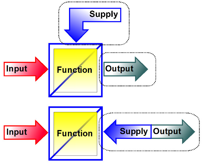
4-20mA External Source or Input Sourced Concept
Why 4 to 20mA?
The most popular process control signal still used today is 4 to 20mA. It has a number of advantages over zero based and voltage signals.
- Live Zero Commencement of the scale at 4mA, clearly distinguishes between zero and failure conditions of the signal.
- Loop Power Signal below 4mA can be utilised to provide power to a loop or signal powered type of transmitter.
- Noise Immunity The signal information is contained in the 16mA swing (20 - 4). The receiving instrument has typically a low input resistance (10 to 250Ω) which will render the current signal highly immune to electrical interference.
- Long Cable Length The signal produced by the sensor/transmitter remains constant up to a specified maximum load resistance, so that type and length of cabling used is of little consequence.
- Safety The low drive voltage required, usually 12 to 24Vdc provides a very high degree of safety.

Auxiliary Powered Transmitter Concept
4-20mA Input Powered
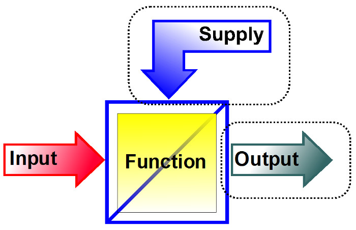
The drive for the 4 to 20mA is derived from the input device.
This current 4mA = 0% of output to 20mA 100% of output also powers the APCS signal conditioning module.

4-20mA Loop Input Powered Concept
dc A Input
Select products that accept 1Adc or more. For lower currents use the dc mA/V input selection.
The load current to be measured is wired in series with an internal shunt or passes through a Hall Effect Current Transformer.

Shunts Inputs
Some products have an internal wired in series with the load current.
The shunt is a low value accurate resistor. The voltage drop across the shunt is E = I × R.
An accurate millivolt amplifier is then used to create an accurate measurement.
External shunts can also be used with mV measurement products.

50A Shunt
Hall Effect Inputs
The DCT247/8 has a top mounted hall effect CT with link selected ranges from 1A to 100A. For higher currents the DCT247/8 may be used with a range of external hall effect CT’s.
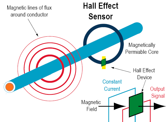
The current conductor passes through a magnetically permeable core that concentrates the conductor’s magnetic field. The Hall effect device is mounted in the core at a right angle to the concentrated magnetic field. When the energised Hall device is exposed to a magnetic field from the core, it produces a potential difference (voltage) that can be measured and amplified.

Hall Effect Sensor
dc mA/V mA and V Input
This selects products that cover the common process signal inputs.
Common process signals include: 4..20mA, 1..5V, 0..20mA, 0..10V, 10..50mA, 0..10mA, 0..1V and 0..5V.

dc mV Input
This selects products that include a high gain precision amplifier that will scale the small input signal to a level stable for processing.
mV transmitters and isolators are used in a wide range of applications where the signal from the sensing probe needs amplification before use.
