Pulse & Relay Outputs
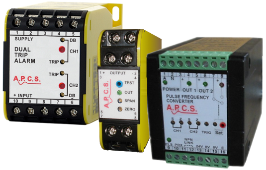
Outputs may be transistor, voltage pulse or a relay contact. The period T of a continuously occurring pulse is the time to complete one cycle while the frequency is the inverse of the period can be measured as a frequency f.
Find a Product Output ⇒ Function ⇒ Input
- Pulse/ Frequency
- Pulse/ Frequency, Select a Function
- Isolator
- Pulse/ Frequency Isolator, Select Input Group
- ac A
- Pulse/ Frequency Isolator ac A, Select Product
- APC258 Analogue to Pulse Converter

- ac V
- Pulse/ Frequency Isolator ac V, Select Product
- APC258 Analogue to Pulse Converter

- 4-20mA
- Pulse/ Frequency Isolator 4-20mA, Select Product
- APC258 Analogue to Pulse Converter
- PWM157 Analog To PWM

- dc A
- Pulse/ Frequency Isolator dc A, Select Product
- APC258 Analogue to Pulse Converter

- dc mA/V
- Pulse/ Frequency Isolator dc mA/V, Select Product
- APC258 Analogue to Pulse Converter
- PWM157 Analog To PWM

- mV
- Pulse/ Frequency Isolator mV, Select Product
- APC258 Analogue to Pulse Converter

- RTD
- Pulse/ Frequency Isolator RTD, Select Product
- APC258 Analogue to Pulse Converter

- pH/REDOX
- Pulse/ Frequency Isolator pH/REDOX, Select Product
- APC258 Analogue to Pulse Converter

- Potentiometer
- Pulse/ Frequency Isolator Potentiometer, Select Product
- APC258 Analogue to Pulse Converter

- Resistance
- Pulse/ Frequency Isolator Resistance, Select Product
- APC258 Analogue to Pulse Converter

- Speed/ Frequency/ Pulse
- Pulse/ Frequency Isolator Speed/ Frequency/ Pulse, Select Product
- PLS257 Pulse Splitter
- APC258 Analogue to Pulse Converter


- Transmitter
- Pulse/ Frequency Transmitter, Select Input Group
- ac A
- Pulse/ Frequency Transmitter ac A, Select Product
- APC258 Analogue to Pulse Converter

- ac V
- Pulse/ Frequency Transmitter ac V, Select Product
- APC258 Analogue to Pulse Converter

- 4-20mA
- Pulse/ Frequency Transmitter 4-20mA, Select Product
- APC258 Analogue to Pulse Converter
- PWM157 Analog To PWM

- dc A
- Pulse/ Frequency Transmitter dc A, Select Product
- APC258 Analogue to Pulse Converter

- dc mA/V
- Pulse/ Frequency Transmitter dc mA/V, Select Product
- APC258 Analogue to Pulse Converter
- PWM157 Analog To PWM

- mV
- Pulse/ Frequency Transmitter mV, Select Product
- APC258 Analogue to Pulse Converter

- RTD
- Pulse/ Frequency Transmitter RTD, Select Product
- APC258 Analogue to Pulse Converter

- pH/REDOX
- Pulse/ Frequency Transmitter pH/REDOX, Select Product
- APC258 Analogue to Pulse Converter

- Potentiometer
- Pulse/ Frequency Transmitter Potentiometer, Select Product
- APC258 Analogue to Pulse Converter

- Resistance
- Pulse/ Frequency Transmitter Resistance, Select Product
- APC258 Analogue to Pulse Converter

- Speed/ Frequency/ Pulse
- Pulse/ Frequency Transmitter Speed/ Frequency/ Pulse, Select Product
- PLS257 Pulse Splitter
- APC258 Analogue to Pulse Converter


- Relay
- Relay, Select a Function
- ac Transducer
- Relay ac Transducer, Select Input Group
- ac V
- Relay ac Transducer ac V, Select Product
- VPR271 Voltage Presence Relay

- Signal Powered
- Relay ac Transducer Signal Powered, Select Product
- VPR271 Voltage Presence Relay


- Alarm
- Relay Alarm, Select Input Group
- ac A
- Relay Alarm ac A, Select Product
- DTA137 Dual Trip Alarm
- STA138 Single Trip Alarm
- DCA218 dc Current Alarm
- CM270 Current Monitor
- DTI135 Dual Trippoint Isolator
- STI136 Single Trippoint Isolator

- ac V
- Signal Powered
- Relay Alarm Signal Powered, Select Product
- VPR271 Voltage Presence Relay
- STI136 Single Trippoint Isolator
- HVR272 High Voltage Relay

- 4-20mA
- Relay Alarm 4-20mA, Select Product
- DTA137 Dual Trip Alarm
- STA138 Single Trip Alarm
- TRA173 Triple Trip Alarm
- DTI135 Dual Trippoint Isolator
- STI136 Single Trippoint Isolator

- dc A
- Relay Alarm dc A, Select Product
- DCA218 dc Current Alarm

- dc mA/V
- Relay Alarm dc mA/V, Select Product
- DTA137 Dual Trip Alarm
- STA138 Single Trip Alarm
- TRA173 Triple Trip Alarm
- DTI135 Dual Trippoint Isolator
- STI136 Single Trippoint Isolator

- mV
- Relay Alarm mV, Select Product
- DTI135 Dual Trippoint Isolator
- STI136 Single Trippoint Isolator

- RTD
- Relay Alarm RTD, Select Product
- DTA137 Dual Trip Alarm
- STA138 Single Trip Alarm
- DTI135 Dual Trippoint Isolator
- STI136 Single Trippoint Isolator

- Thermocouple
- Relay Alarm Thermocouple, Select Product
- DTA137 Dual Trip Alarm
- STA138 Single Trip Alarm
- DTI135 Dual Trippoint Isolator
- STI136 Single Trippoint Isolator

- Conductivity
- Relay Alarm Conductivity, Select Product
- DTA137 Dual Trip Alarm
- STA138 Single Trip Alarm
- LLD207 Liquid Level Detector

- pH/REDOX
- Relay Alarm pH/REDOX, Select Product
- DTA137 Dual Trip Alarm
- STA138 Single Trip Alarm

- Potentiometer
- Relay Alarm Potentiometer, Select Product
- DTA137 Dual Trip Alarm
- STA138 Single Trip Alarm
- DTI135 Dual Trippoint Isolator
- STI136 Single Trippoint Isolator

- Pressure
- Relay Alarm Pressure, Select Product
- PM276 Pressure Monitor
- PM277 Differential Pressure Monitor

- Resistance
- Relay Alarm Resistance, Select Product
- DTA137 Dual Trip Alarm
- STA138 Single Trip Alarm
- DTI135 Dual Trippoint Isolator
- STI136 Single Trippoint Isolator

- Speed/ Frequency/ Pulse
- Relay Alarm Speed/ Frequency/ Pulse, Select Product
- DTA137 Dual Trip Alarm
- STA138 Single Trip Alarm
- DTI135 Dual Trippoint Isolator
- STI136 Single Trippoint Isolator
- FRA251 Frequency Alarm

- Strain Gauge
- Relay Alarm Strain Gauge, Select Product
- DTA137 Dual Trip Alarm
- STA138 Single Trip Alarm


- Isolator
- Relay Isolator, Select Input Group
- ac A
- Relay Isolator ac A, Select Product
- DTI135 Dual Trippoint Isolator
- STI136 Single Trippoint Isolator

- ac V
- Relay Isolator ac V, Select Product
- DTI135 Dual Trippoint Isolator
- STI136 Single Trippoint Isolator

- Signal Powered
- Relay Isolator Signal Powered, Select Product
- STI136 Single Trippoint Isolator

- 4-20mA
- Relay Isolator 4-20mA, Select Product
- DTI135 Dual Trippoint Isolator
- STI136 Single Trippoint Isolator

- dc mA/V
- Relay Isolator dc mA/V, Select Product
- DTI135 Dual Trippoint Isolator
- STI136 Single Trippoint Isolator

- mV
- Relay Isolator mV, Select Product
- DTI135 Dual Trippoint Isolator
- STI136 Single Trippoint Isolator

- RTD
- Relay Isolator RTD, Select Product
- DTI135 Dual Trippoint Isolator
- STI136 Single Trippoint Isolator

- Thermocouple
- Relay Isolator Thermocouple, Select Product
- DTI135 Dual Trippoint Isolator
- STI136 Single Trippoint Isolator

- Potentiometer
- Relay Isolator Potentiometer, Select Product
- DTI135 Dual Trippoint Isolator
- STI136 Single Trippoint Isolator

- Resistance
- Relay Isolator Resistance, Select Product
- DTI135 Dual Trippoint Isolator
- STI136 Single Trippoint Isolator

- Speed/ Frequency/ Pulse
- Relay Isolator Speed/ Frequency/ Pulse, Select Product
- DTI135 Dual Trippoint Isolator
- STI136 Single Trippoint Isolator


- Transmitter
- Relay Transmitter, Select Input Group
- ac A
- Relay Transmitter ac A, Select Product
- DTI135 Dual Trippoint Isolator
- STI136 Single Trippoint Isolator

- ac V
- Relay Transmitter ac V, Select Product
- DTI135 Dual Trippoint Isolator
- STI136 Single Trippoint Isolator

- Signal Powered
- Relay Transmitter Signal Powered, Select Product
- STI136 Single Trippoint Isolator

- 4-20mA
- Relay Transmitter 4-20mA, Select Product
- DTI135 Dual Trippoint Isolator
- STI136 Single Trippoint Isolator

- dc mA/V
- Relay Transmitter dc mA/V, Select Product
- DTI135 Dual Trippoint Isolator
- STI136 Single Trippoint Isolator

- mV
- Relay Transmitter mV, Select Product
- DTI135 Dual Trippoint Isolator
- STI136 Single Trippoint Isolator

- RTD
- Relay Transmitter RTD, Select Product
- DTI135 Dual Trippoint Isolator
- STI136 Single Trippoint Isolator

- Thermocouple
- Relay Transmitter Thermocouple, Select Product
- DTI135 Dual Trippoint Isolator
- STI136 Single Trippoint Isolator

- Potentiometer
- Relay Transmitter Potentiometer, Select Product
- DTI135 Dual Trippoint Isolator
- STI136 Single Trippoint Isolator

- Resistance
- Relay Transmitter Resistance, Select Product
- DTI135 Dual Trippoint Isolator
- STI136 Single Trippoint Isolator

- Speed/ Frequency/ Pulse
- Relay Transmitter Speed/ Frequency/ Pulse, Select Product
- DTI135 Dual Trippoint Isolator
- STI136 Single Trippoint Isolator


- Pilot Cable Monitor
- Relay Pilot Cable Monitor, Select Input Group
- Conductivity
- Relay Pilot Cable Monitor Conductivity, Select Product
- PCM177 Pilot Cable Monitor

- Resistance
- Relay Pilot Cable Monitor Resistance, Select Product
- PCM177 Pilot Cable Monitor


- Select an Output (above)

Outputs may be transistor, voltage pulse or a relay contact. The period T of a continuously occurring pulse is the time to complete one cycle while the frequency is the inverse of the period can be measured as a frequency f.

Pulse/Frequency Output

Pulse outputs are produced using solid state means while relay outputs have a mechanical component. Pulse outputs may have a specified amplitude or may be require external components to complete the circuit before the output signal can be measured which is typical of an open collector output.
The diagram shows a block diagram of an APC153 connected to an output load between terminals 8 and 10.
- The output load represents the input of the receiving equipment or a pull up resistor.
- Current Ip flows when the output transistor is ON or is zero when OFF.
- The APC153 conveniently provides an isolated power supply for use as the pull up voltage, this power supply could be part of the receiving equipment.
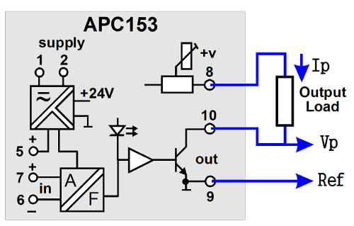
APC153 connected to an output load
- The emitter of the NPN transistor is connected internally to the output power supply and acts as a reference if wanting to monitor the voltage of the output pulse. The voltage is close to 0 when the transistor is ON and rises to the voltage at terminal 8 when OFF.
- If the receiving instrument is a current input only the connections at 8 and 10 are required.
- If the receiving instrument is a voltage input then a pull up is required between 8 and 10 typically 1kohm is required and the input is connected to 9 and 10.
Connections will vary if pull up resistor and or pull up power is provided by the receiving instrument. It is important to remember that the output transistor cannot directly switch the full power supply current, a pull up is required. When using the APC153 the provided pull up power supply has a current limit lower than the raring of the output transistor making wiring mistakes more forgiving. When using a product it is important to look at the maximum current and voltage rating of the output transistor.
| APC153 Output Specification | |
|---|---|
| Output frequency range | 10Hz to 10kHz. |
| Pulse voltage level | 1.0 up to 24Vdc (adjustable). |
| Output pulse drive | 20mA maximum. |
| Output transistor | 30V, 100mA. |
| Input/output isolation | 1000Vrms/1500Vdc. |
Relay Output
Relay outputs or contacts have the advantage of being mechanically isolated from the measuring device and usually have higher voltage ratings than solid state devices however the number of switching operations over a lifetime is lower.
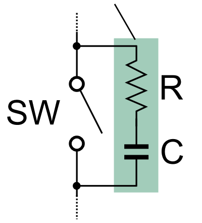
APCS modules do not have a snubber circuit fitted to relay contact outputs and are specified with resistive loads. Appropriate measures must be made when using relay contact outputs. If switching an inductive load a snubber is required to reduce the sharp rise in voltage causing arching across the contacts. The snubber provides a short-term alternative current path so that the inductive element may be discharged. When using a product it is important to look at the maximum current and voltage rating of the relay contact and what type of load is is specified for (eg Relay contact: 8A/250V resistive, 3.5A/250V inductive).