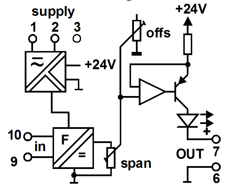
ac Input Conditioning
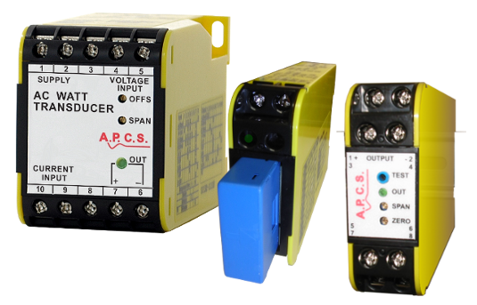
Select products that measure ac input parameters and produce a standard process signal output or an alarm state.
AC refers to Alternating Current, this is a flow of electric charge that periodically reverses direction. Most electricity is delivered to homes and businesses usually in sine wave form at a fixed frequency.
Magnetic sensors on rotating machinery produce a variable frequency and amplitude output that is used in a variety of ways.
Find a Product Input ⇒ Function ⇒ Output
- ac A
- ac A, Select Function
- ac Transducer
- ac A ac Transducer, Select Output
- 4-20mA 2-Wire
- ac A ac Transducer 4-20mA 2-Wire, Select Product
- ACT241 ac Current Transducer

- 4-20mA 4-Wire
- ac A ac Transducer 4-20mA 4-Wire, Select Product
- SL345 AC and Bipolar Isolator
- DCT247 Dc Current Transducer
- ACT284 ac Transducer
- ACT141 ac Current Transducer

- dc mA/V 3-Wire
- ac A ac Transducer dc mA/V 3-Wire, Select Product
- ACT241 ac Current Transducer

- dc mA/V 4-Wire
- ac A ac Transducer dc mA/V 4-Wire, Select Product
- SL345 AC and Bipolar Isolator
- DCT247 Dc Current Transducer
- ACT284 ac Transducer
- ACT141 ac Current Transducer


- Alarm
- ac A Alarm, Select Output
- 4-20mA 4-Wire
- ac A Alarm 4-20mA 4-Wire, Select Product
- DTI135 Dual Trippoint Isolator
- STI136 Single Trippoint Isolator

- dc mA/V 4-Wire
- ac A Alarm dc mA/V 4-Wire, Select Product
- DTI135 Dual Trippoint Isolator
- STI136 Single Trippoint Isolator

- Relay
- ac A Alarm Relay, Select Product
- DTA137 Dual Trip Alarm
- STA138 Single Trip Alarm
- DCA218 dc Current Alarm
- CM270 Current Monitor
- DTI135 Dual Trippoint Isolator
- STI136 Single Trippoint Isolator


- Isolator
- ac A Isolator, Select Output
- 4-20mA 2-Wire
- ac A Isolator 4-20mA 2-Wire, Select Product
- ACT241 ac Current Transducer

- 4-20mA 4-Wire
- ac A Isolator 4-20mA 4-Wire, Select Product
- SL345 AC and Bipolar Isolator
- DCT247 Dc Current Transducer
- ACT284 ac Transducer
- ACT141 ac Current Transducer
- DTI135 Dual Trippoint Isolator
- STI136 Single Trippoint Isolator

- dc mA/V 3-Wire
- ac A Isolator dc mA/V 3-Wire, Select Product
- ACT241 ac Current Transducer

- dc mA/V 4-Wire
- ac A Isolator dc mA/V 4-Wire, Select Product
- SL345 AC and Bipolar Isolator
- DCT247 Dc Current Transducer
- ACT284 ac Transducer
- ACT141 ac Current Transducer
- DTI135 Dual Trippoint Isolator
- STI136 Single Trippoint Isolator

- Pulse/ Frequency
- ac A Isolator Pulse/ Frequency, Select Product
- APC258 Analogue to Pulse Converter

- Relay
- ac A Isolator Relay, Select Product
- DTI135 Dual Trippoint Isolator
- STI136 Single Trippoint Isolator


- Transmitter
- ac A Transmitter, Select Output
- 4-20mA 2-Wire
- ac A Transmitter 4-20mA 2-Wire, Select Product
- ACT241 ac Current Transducer

- 4-20mA 4-Wire
- ac A Transmitter 4-20mA 4-Wire, Select Product
- SL345 AC and Bipolar Isolator
- DCT247 Dc Current Transducer
- ACT284 ac Transducer
- ACT141 ac Current Transducer
- DTI135 Dual Trippoint Isolator
- STI136 Single Trippoint Isolator

- dc mA/V 3-Wire
- ac A Transmitter dc mA/V 3-Wire, Select Product
- ACT241 ac Current Transducer

- dc mA/V 4-Wire
- ac A Transmitter dc mA/V 4-Wire, Select Product
- SL345 AC and Bipolar Isolator
- DCT247 Dc Current Transducer
- ACT284 ac Transducer
- ACT141 ac Current Transducer
- DTI135 Dual Trippoint Isolator
- STI136 Single Trippoint Isolator

- Bipolar
- ac A Transmitter Bipolar, Select Product
- BSC133 Bipolar Signal Converter

- High Drive
- ac A Transmitter High Drive, Select Product
- BSC133 Bipolar Signal Converter

- Pulse/ Frequency
- ac A Transmitter Pulse/ Frequency, Select Product
- APC258 Analogue to Pulse Converter

- Relay
- ac A Transmitter Relay, Select Product
- DTI135 Dual Trippoint Isolator
- STI136 Single Trippoint Isolator


- ac Power
- ac Power, Select Function
- ac Transducer
- ac Power ac Transducer, Select Output
- 4-20mA 4-Wire
- ac Power ac Transducer 4-20mA 4-Wire, Select Product
- AWT190 Ac Active Power Transducer
- ART191 Ac Active VAR Transducer
- AVAT192 ac Active VA Transducer
- APT193 Ac Active Phase Angle Trans.

- dc mA/V 4-Wire
- ac Power ac Transducer dc mA/V 4-Wire, Select Product
- AWT190 Ac Active Power Transducer
- ART191 Ac Active VAR Transducer
- AVAT192 ac Active VA Transducer
- APT193 Ac Active Phase Angle Trans.

- Bipolar
- ac Power ac Transducer Bipolar, Select Product
- AWT190 Ac Active Power Transducer
- ART191 Ac Active VAR Transducer
- AVAT192 ac Active VA Transducer
- APT193 Ac Active Phase Angle Trans.


- ac V
- ac V, Select Function
- ac Transducer
- ac V ac Transducer, Select Output
- 4-20mA 2-Wire
- ac V ac Transducer 4-20mA 2-Wire, Select Product
- AVT245 ac Voltage Transducer

- 4-20mA 4-Wire
- ac V ac Transducer 4-20mA 4-Wire, Select Product
- SL345 AC and Bipolar Isolator
- SL350 Pulse Frequency Transmitter
- ACT284 ac Transducer
- AVT145 Ac Voltage Transmitter

- dc mA/V 3-Wire
- ac V ac Transducer dc mA/V 3-Wire, Select Product
- AVT245 ac Voltage Transducer

- dc mA/V 4-Wire
- ac V ac Transducer dc mA/V 4-Wire, Select Product
- SL345 AC and Bipolar Isolator
- SL350 Pulse Frequency Transmitter
- ACT284 ac Transducer
- AVT145 Ac Voltage Transmitter

- Relay
- ac V ac Transducer Relay, Select Product
- VPR271 Voltage Presence Relay


- Alarm
- ac V Alarm, Select Output
- 4-20mA 4-Wire
- ac V Alarm 4-20mA 4-Wire, Select Product
- DTI135 Dual Trippoint Isolator
- STI136 Single Trippoint Isolator

- dc mA/V 4-Wire
- ac V Alarm dc mA/V 4-Wire, Select Product
- DTI135 Dual Trippoint Isolator
- STI136 Single Trippoint Isolator

- Relay

- Isolator
- ac V Isolator, Select Output
- 4-20mA 2-Wire
- ac V Isolator 4-20mA 2-Wire, Select Product
- SI239 Signal Isolator
- AVT245 ac Voltage Transducer

- 4-20mA 4-Wire
- ac V Isolator 4-20mA 4-Wire, Select Product
- SL345 AC and Bipolar Isolator
- SL350 Pulse Frequency Transmitter
- ACT284 ac Transducer
- AVT145 Ac Voltage Transmitter
- DTI135 Dual Trippoint Isolator
- STI136 Single Trippoint Isolator
- SI139 Signal Isolator

- dc mA/V 3-Wire
- ac V Isolator dc mA/V 3-Wire, Select Product
- SI239 Signal Isolator
- AVT245 ac Voltage Transducer

- dc mA/V 4-Wire
- ac V Isolator dc mA/V 4-Wire, Select Product
- SL345 AC and Bipolar Isolator
- SL350 Pulse Frequency Transmitter
- ACT284 ac Transducer
- AVT145 Ac Voltage Transmitter
- DTI135 Dual Trippoint Isolator
- STI136 Single Trippoint Isolator
- SI139 Signal Isolator

- Pulse/ Frequency
- ac V Isolator Pulse/ Frequency, Select Product
- APC258 Analogue to Pulse Converter

- Relay
- ac V Isolator Relay, Select Product
- DTI135 Dual Trippoint Isolator
- STI136 Single Trippoint Isolator


- Transmitter
- ac V Transmitter, Select Output
- 4-20mA 2-Wire
- ac V Transmitter 4-20mA 2-Wire, Select Product
- SI239 Signal Isolator
- AVT245 ac Voltage Transducer

- 4-20mA 4-Wire
- ac V Transmitter 4-20mA 4-Wire, Select Product
- SL345 AC and Bipolar Isolator
- SL350 Pulse Frequency Transmitter
- ACT284 ac Transducer
- AVT145 Ac Voltage Transmitter
- DTI135 Dual Trippoint Isolator
- STI136 Single Trippoint Isolator
- SI139 Signal Isolator

- dc mA/V 3-Wire
- ac V Transmitter dc mA/V 3-Wire, Select Product
- SI239 Signal Isolator
- AVT245 ac Voltage Transducer

- dc mA/V 4-Wire
- ac V Transmitter dc mA/V 4-Wire, Select Product
- SL345 AC and Bipolar Isolator
- SL350 Pulse Frequency Transmitter
- ACT284 ac Transducer
- AVT145 Ac Voltage Transmitter
- DTI135 Dual Trippoint Isolator
- STI136 Single Trippoint Isolator
- SI139 Signal Isolator

- Bipolar
- ac V Transmitter Bipolar, Select Product
- BSC133 Bipolar Signal Converter

- High Drive
- ac V Transmitter High Drive, Select Product
- BSC133 Bipolar Signal Converter

- Pulse/ Frequency
- ac V Transmitter Pulse/ Frequency, Select Product
- APC258 Analogue to Pulse Converter

- Relay
- ac V Transmitter Relay, Select Product
- DTI135 Dual Trippoint Isolator
- STI136 Single Trippoint Isolator


- Signal Powered
- Signal Powered, Select Function
- ac Transducer
- Signal Powered ac Transducer, Select Output
- Relay
- Signal Powered ac Transducer Relay, Select Product
- VPR271 Voltage Presence Relay


- Alarm
- Signal Powered Alarm, Select Output
- 4-20mA 4-Wire
- Signal Powered Alarm 4-20mA 4-Wire, Select Product
- STI136 Single Trippoint Isolator

- dc mA/V 4-Wire
- Signal Powered Alarm dc mA/V 4-Wire, Select Product
- STI136 Single Trippoint Isolator

- Relay
- Signal Powered Alarm Relay, Select Product
- VPR271 Voltage Presence Relay
- STI136 Single Trippoint Isolator
- HVR272 High Voltage Relay


- Isolator
- Signal Powered Isolator, Select Output
- 4-20mA 4-Wire
- Signal Powered Isolator 4-20mA 4-Wire, Select Product
- STI136 Single Trippoint Isolator

- dc mA/V 4-Wire
- Signal Powered Isolator dc mA/V 4-Wire, Select Product
- STI136 Single Trippoint Isolator

- Relay
- Signal Powered Isolator Relay, Select Product
- STI136 Single Trippoint Isolator


- Transmitter
- Signal Powered Transmitter, Select Output
- 4-20mA 4-Wire
- Signal Powered Transmitter 4-20mA 4-Wire, Select Product
- STI136 Single Trippoint Isolator

- dc mA/V 4-Wire
- Signal Powered Transmitter dc mA/V 4-Wire, Select Product
- STI136 Single Trippoint Isolator

- Relay
- Signal Powered Transmitter Relay, Select Product
- STI136 Single Trippoint Isolator


- Select a Input (above)

Select products that measure ac input parameters and produce a standard process signal output or an alarm state.
AC refers to Alternating Current, this is a flow of electric charge that periodically reverses direction. Most electricity is delivered to homes and businesses usually in sine wave form at a fixed frequency.
Magnetic sensors on rotating machinery produce a variable frequency and amplitude output that is used in a variety of ways.

ac A Alternating Current
Select products that measure Alternating Current, and produce a standard process signal output or an alarm state.
Most ac measurements are based on a fixed 50/60Hz sine wave. The measurement circuit typically average responding.
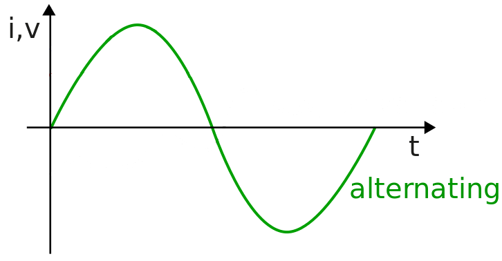
Alternating Current Sine Wave
acA Average Responding Transducer
The standard method for measuring the magnitude of an ac signal is to use a precision rectifier followed by a filter. This measures the “average” value. A scale factor is calibrated into the measurement (which is the ratio of rms to average for sine waves).
This is sufficient as long as the input waveform is an undistorted sine wave. Acceptable results are achieved provided the waveform to be measured has no greater than a few percent distortion. If the input has high distortion, it should be measured with an rms responding instrument. For better accuracy when measuring non-sinusoidal signals, the measuring instrument should use a rms technique.
Some of our ac measurements are true rms responding.
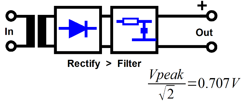
Average Responding Transducer
rms Responding Transducer
Root Mean Square (rms) is a fundamental measurement of the magnitude of an ac signal. The rms value assigned to an ac signal is the amount of dc required to produce an equivalent amount of heat in the same load. Many measurements are made during each cycle of the input to measure areas of energy in the input independent of the wave shape. An rms result is calculated at the end of each cycle.
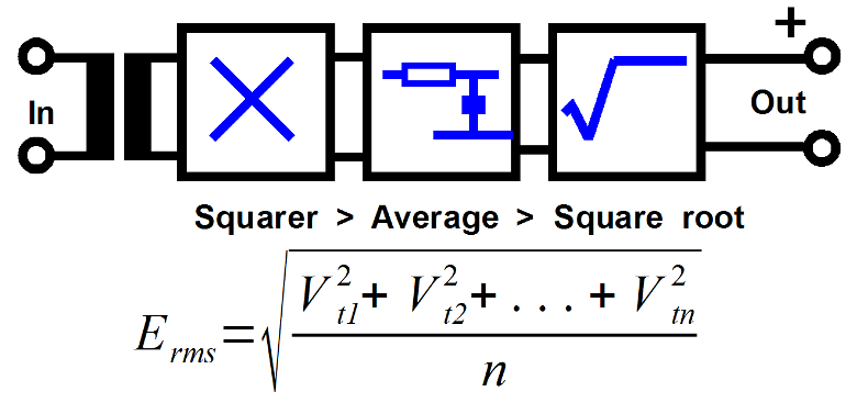
rms Responding Transducer block diagram
A current Transformer (CT) is an electric device that produces an alternating current (AC) in its secondary which is proportional to the AC in its primary.
A Voltage Transformer (VT) or potential transformers (PT) also known as measurement transformers are used when the voltage is too high to directly connect directly to the measuring instrument.
The block diagrams above show an internal CT typically 5A rated, higher currents may be measured with an external CT added to the circuit.
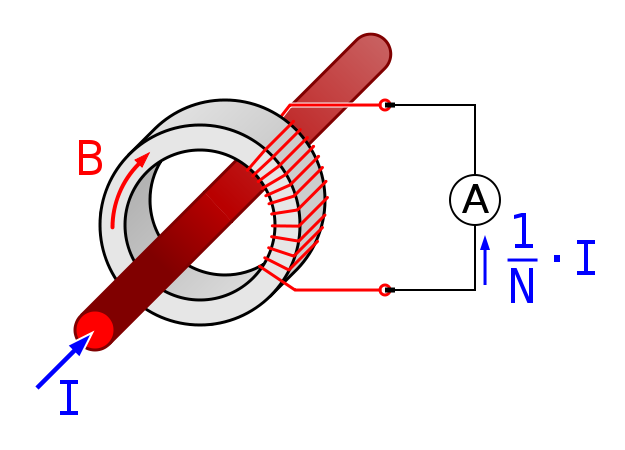
Basic Current Transformer Theory
Some APCS DC Current modules are also selected in the ac Measurement section. This is because they have a HALL Effect CT fitted and a true rms measurement option for accurate measurement regardless of the wave shape.
The Hall effect sensor has a core, Hall effect device and signal conditioning circuitry. The current conductor passes through a magnetically permeable core that concentrates the conductor’s magnetic field.
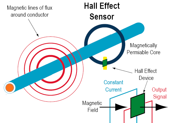
Hall Effect Sensor
The Hall effect device is mounted in the core at a right angle to the concentrated magnetic field. A constant current in one plane excites the Hall device. When the energised Hall device is exposed to a magnetic field from the core, it produces a potential difference (voltage) that can be measured and amplified into process level signals such as 4-20mA or a contact closure.
ac Power
Monitoring ac power is more complex than monitoring ac voltage or current. Transducers provide a dc output which is proportional to the real average power as defined as;
E × I × cos(φ).
The watt transducer is polarity sensitive in that it senses both the power and the direction the power is flowing. Power transducers can be single phase or three phase. Three phase types can be three or four wire ( the fourth wire being the neutral).

Distrubtion Lines
Three Phase Balanced System
In a three phase system, the three voltages are out of phase with each other by 120°. We can represent this vector-ally as shown below. In a balanced load situation (the loads on the 3 phases are equal and draw the same current) the three current vectors are also out of phase with each other by 120°, but each can be at an angle of θ to its corresponding voltage vector. This θ represents the impedance of the load.
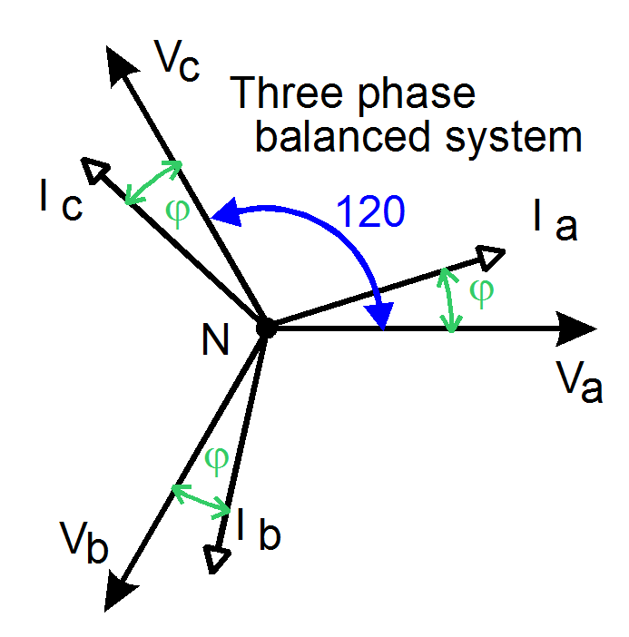
Three Phase Balanced System
Inductive And Capacitive Loads
For resistive loads φ = 0 and the current and voltage vectors are in phase.
For capacitive loads the current will lead the voltage vector by the angle For resistive loads φ = 0 and the current and voltage vectors are in phase.
For capacitive loads the current will lead the voltage vector by the angle φ where φ depends on the relative capacitance and impedance of the load.
For inductive loads the current will lag the voltage vector by the angle θ where θ depends on the relative Inductance and impedance of the load.
For a pure inductor, φ = 90°. For a pure capacitor, φ = -90°.
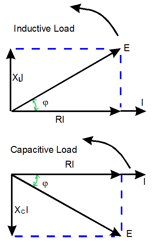
Inductive And Capacitive Vector Relationships
This is most easily seen by rotating vectors. Note that all the vectors are rotating at the same angular velocity which is one revolution per cycle of the voltage signal.
The vector diagram shows the peak ac current flowing through a resistor and inductor in series.
The peak voltage drop (RI) in the resistor is in phase with the current as is shown. The peak voltage drop across the inductor is ωLI = XLI this vector is drawn vertically as it leads the current I by 90°. The resultant peak voltage drop across the total load (E) is formed by the resultant of these two vectors. It is seen that I lags behind E by the angle φ.
Unbalanced Three Phase System
A great advantage that a three phase rotating machine over a single phase machine is that at no time does the instantaneous power drawn by the load reach zero. In fact, the instantaneous power is constant which is a big advantage for rotating machinery because a more constant torque it maintained.
When the load is unbalanced the three current vectors are no longer out of phase with each other by 120°, but each can be at a different angle to its corresponding voltage vector. However, the vectorial sum of the three current vectors must equal zero (Ia + Ib + Ic = 0 Kirchoff’s Law).
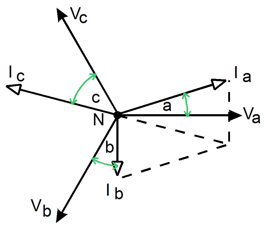
Unbalanced Three Phase System
Power: Real, Reactive or Apparent ?
Real Power (watts) = the power value converted to an energy form at the load.
When the load has a greater inductive factor, more current is required to create the same real power.
Watts is given by:
- W = E × I × cos(φ) for single phase.
- W = Epn × I × cos(φ) for 3 phase (Epn = phase to neutral voltage)
- W = √3 × Epp × I × cos(φ) for 3 phase (Epp = phase to phase voltage)
cos(φ) = the power factor, is the cosine of the angle between the voltage and the current.
Reactive Power = the value which is not converted into energy. It is a measure of the power required to establish electromagnetic fields in the installation- e.g. in motors, solenoids and light fittings.
The unit is VAr (volt amp reactive). VAr = E × I × sin(φ).
Apparent Power is the power calculated by simple multiplication of the voltage by the current (VA = E × I). The unit is VA.
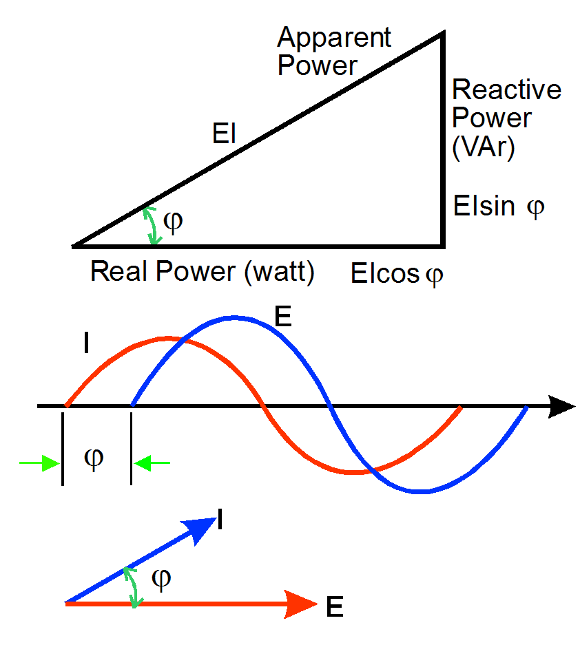
ac Vector Relationships
Three Phase Watt Measurement
The diagram shows a three phase source connected to a STAR (or WYE) load.
This is also referred to as a three phase, four wire load.
Here, we need to monitor the current in all three phase lines. The total power delivered to the load is the sum of the power measured in each phase. The Watt transducer output will be constant for a constant load.
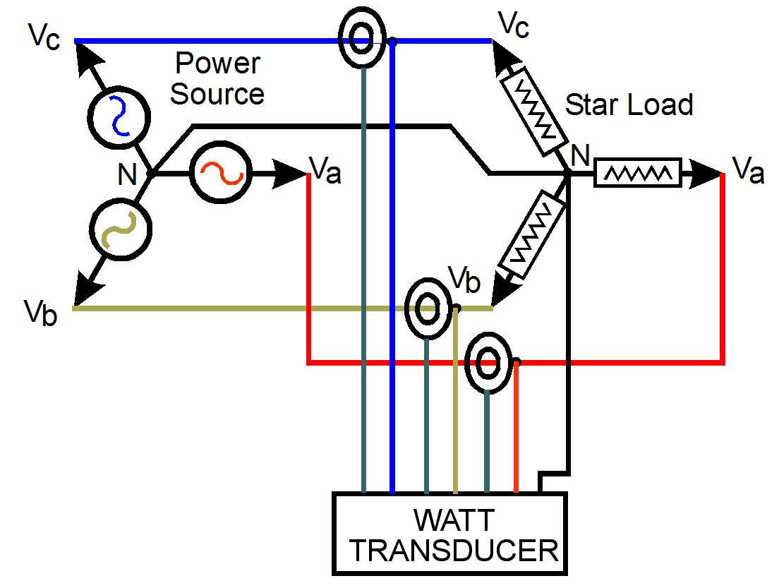
Three Phase Star Connection
Three Phase DELTA load Connection
This diagram shows the connection for a three phase source connected to a DELTA load.
This is also referred to as a three phase, three wire load’
According to Blondel’s theorem, in an n wire system we only need to measure n - 1 elements (here we only need two multiplier elements).
E.g. for 3 phase 3 wire unbalanced load:
W = Va × Ia + Vb × Ib + Vc × Ic
i.e. W = Va × Ia + Vb × ( Ia - Ic ) + Vc × Ic
since Ia + Ib + Ic = 0
W = (Va - Vb ) × Ia + ( Vc - Vb ) × Ic = Vba × Ia + Vbc × Ic
We only need 2 multiplying elements not 3, and only 2 external CT, a savings in cost.
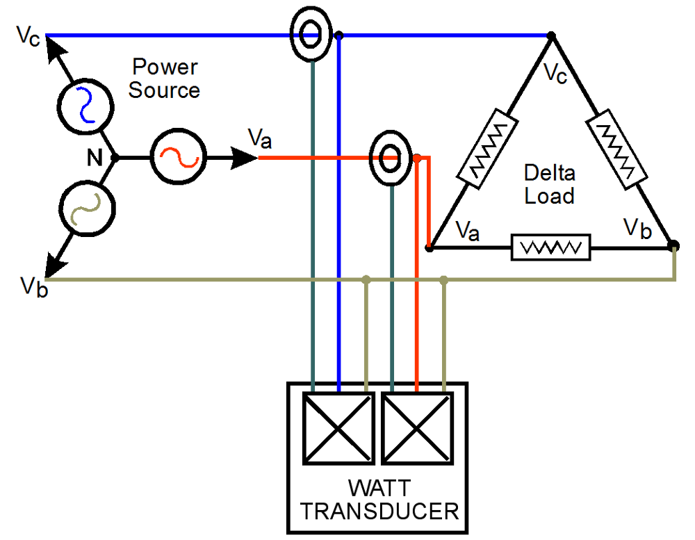
Three Phase DELTA load Connection
Power Factor
Power Factor is a measure of the proportion of apparent power consumed by the installation which is actually put to productive use.
The higher the power factor, the less VA or amps has to be supplied to provide the same watts output. Poor power factor can and should be remedied by the use of power factor correction
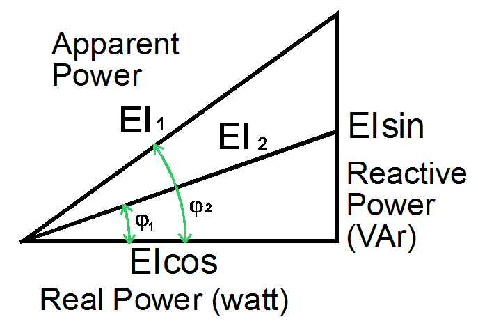
Power Factor
Consider a typical installation of 100 single 36W light batons. Each baton might have a PF of 0.45 and a load of 0.625A. i.e. the total load is 62.5A.
If these were replaced by High Power Factor fittings - which consist basically of an added capacitor- then the PF increases to 0.9 and the total load decreases to 37A. This provides an advantage of a large reduction in running costs, in load, in cabling and in the number of circuit breakers.
PF can range from unity (ideal) to zero. The higher the PF the more apparent power (the power you pay for on your kVA tariff) is turned into real power (the power you actually use).
Power Factor Transducers are used to measure the power factor of an installation so that power factor correction can be optimised. The measurement technique is to calculate the true power E × I × cos(φ) and divide this value by the Apparent power E × I. This gives the required cos(φ).
An simpler acceptable answer is obtained for single phase and 3 phase balanced load situations by using a Phase Angle transducer. This transducer has its dc output proportional to the phase angle difference between the current and voltage (rather than the cosine of this angle). This output can be used for controlling the power factor correction or for monitoring.
The principle of operation for a Phase Angle transducer is generally to detect the zero crossings of the current and voltage inputs and then using these signals to control a bistable multi-vibrator. The output from this is then filtered and amplified.
ac V Alternating Voltage
Select products that measure Alternating Voltage, and produce a standard process signal output or an alarm state.
Most ac measurements are based on a fixed 50/60Hz sine wave. The measurement circuit typically average responding.

Alternating Current Sine Wave
acV Average Responding Transducer
The standard method for measuring the magnitude of an ac signal is to use a precision rectifier followed by a filter. This measures the “average” value. A scale factor is calibrated into the measurement (which is the ratio of rms to average for sine waves).
This is sufficient as long as the input waveform is an undistorted sine wave. Acceptable results are achieved provided the waveform to be measured has no greater than a few percent distortion.
rms Responding Transducer
Root Mean Square (rms) is a fundamental measurement of the magnitude of an ac signal. The rms value assigned to an ac signal is the amount of dc required to produce an equivalent amount of heat in the same load.
Mathematically, the rms value of a voltage is defined as :
- Erms = √[ ( V2t1 + V2t2 + . . . + V2tn ) / n ]
i.e. Square the instantaneous value, average these values over a period of time, and then take the square root of the resultant. The averaging time should be long enough to allow filtering at the lowest frequencies used.
Signal Powered Transducers
Input signal powered ac isolators derive operating power from the measurement parameters, the ac current / voltage being measured.
It must be remembered that all the power required to operate the transducer and power the output signal is derived from the input signal. This may load the signal in some cases.
Signal Powered Transducers require no separate power supply, resulting in lower install cost.
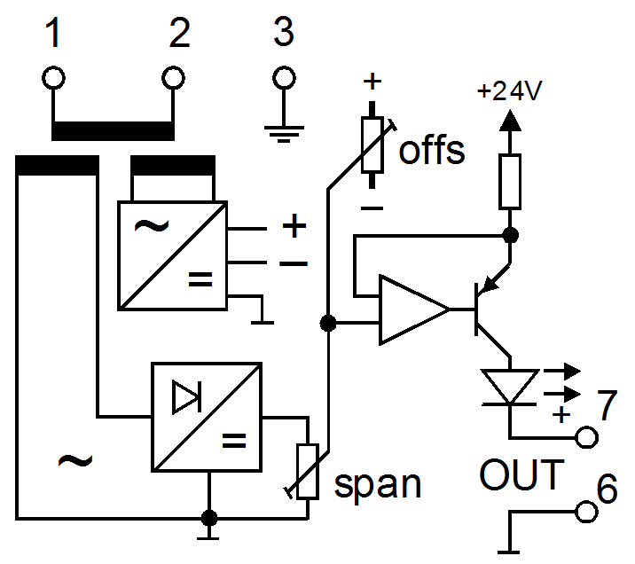
Frequency Transducer
In many cases the frequency of a power supply is critical as equipment such as transformers and motors may draw excessive current or operate at the incorrect speed and fail over time. A frequency transducer or frequency alarm will produce a process signal or alarm output based on a range of input frequency.
