Sensor Conditioning
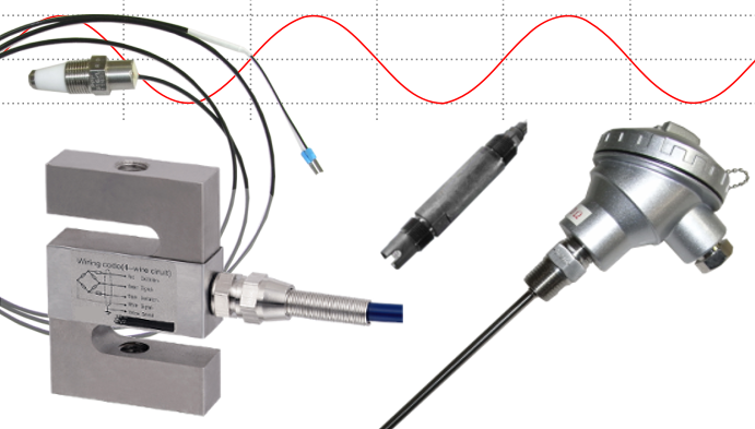
Select products that designed to accept signals from standard industry sensors and produce a standard process signal output or an alarm state.
Process signals are a standardised range in an electrical signal that represent a measured value.
For example a signal of 0 to 10Vdc can represent;
- 100 to 1000kg of butter
- 0 to 100°C ambient temperature.
Find a Product Input ⇒ Function ⇒ Output
- Conductivity
- Conductivity, Select Function
- Alarm
- Conductivity Alarm, Select Output
- Relay
- Conductivity Alarm Relay, Select Product
- DTA137 Dual Trip Alarm
- STA138 Single Trip Alarm
- LLD207 Liquid Level Detector


- Isolator
- Conductivity Isolator, Select Output
- 4-20mA 2-Wire
- Conductivity Isolator 4-20mA 2-Wire, Select Product
- CDT228 Conductivity Transmitter

- 4-20mA 4-Wire
- Conductivity Isolator 4-20mA 4-Wire, Select Product
- CDT128 Conductivity Transmitter

- dc mA/V 3-Wire
- Conductivity Isolator dc mA/V 3-Wire, Select Product
- CDT228 Conductivity Transmitter

- dc mA/V 4-Wire
- Conductivity Isolator dc mA/V 4-Wire, Select Product
- CDT128 Conductivity Transmitter


- Transmitter
- Conductivity Transmitter, Select Output
- 4-20mA 2-Wire
- Conductivity Transmitter 4-20mA 2-Wire, Select Product
- CDT228 Conductivity Transmitter

- 4-20mA 4-Wire
- Conductivity Transmitter 4-20mA 4-Wire, Select Product
- CDT128 Conductivity Transmitter

- dc mA/V 3-Wire
- Conductivity Transmitter dc mA/V 3-Wire, Select Product
- CDT228 Conductivity Transmitter

- dc mA/V 4-Wire
- Conductivity Transmitter dc mA/V 4-Wire, Select Product
- CDT128 Conductivity Transmitter


- Pilot Cable Monitor
- Conductivity Pilot Cable Monitor, Select Output
- Relay
- Conductivity Pilot Cable Monitor Relay, Select Product
- PCM177 Pilot Cable Monitor


- Environmental-z
- Environmental-z, Select Function
- Transmitter
- Environmental-z Transmitter, Select Output
- 4-20mA 2-Wire
- Environmental-z Transmitter 4-20mA 2-Wire, Select Product
- LUX510 LUX Transmitter
- RTT508 Room Temperature Transmitter
- RLT511 Room Light Transmitter

- dc mA/V 3-Wire
- Environmental-z Transmitter dc mA/V 3-Wire, Select Product
- LUX510 LUX Transmitter
- RTT508 Room Temperature Transmitter


- pH/REDOX
- pH/REDOX, Select Function
- Alarm
- pH/REDOX Alarm, Select Output
- Relay
- pH/REDOX Alarm Relay, Select Product
- DTA137 Dual Trip Alarm
- STA138 Single Trip Alarm


- Isolator
- pH/REDOX Isolator, Select Output
- 4-20mA 2-Wire
- pH/REDOX Isolator 4-20mA 2-Wire, Select Product
- PHT229 pH / Redox Transmitter

- 4-20mA 4-Wire
- pH/REDOX Isolator 4-20mA 4-Wire, Select Product
- PHT129 pH / Redox Transmitter

- dc mA/V 3-Wire
- pH/REDOX Isolator dc mA/V 3-Wire, Select Product
- PHT229 pH / Redox Transmitter

- dc mA/V 4-Wire
- pH/REDOX Isolator dc mA/V 4-Wire, Select Product
- PHT129 pH / Redox Transmitter

- Pulse/ Frequency
- pH/REDOX Isolator Pulse/ Frequency, Select Product
- APC258 Analogue to Pulse Converter


- Transmitter
- pH/REDOX Transmitter, Select Output
- 4-20mA 2-Wire
- pH/REDOX Transmitter 4-20mA 2-Wire, Select Product
- PHT229 pH / Redox Transmitter

- 4-20mA 4-Wire
- pH/REDOX Transmitter 4-20mA 4-Wire, Select Product
- PHT129 pH / Redox Transmitter

- dc mA/V 3-Wire
- pH/REDOX Transmitter dc mA/V 3-Wire, Select Product
- PHT229 pH / Redox Transmitter

- dc mA/V 4-Wire
- pH/REDOX Transmitter dc mA/V 4-Wire, Select Product
- PHT129 pH / Redox Transmitter

- Pulse/ Frequency
- pH/REDOX Transmitter Pulse/ Frequency, Select Product
- APC258 Analogue to Pulse Converter


- Position
- Position, Select Function
- Isolator
- Position Isolator, Select Output
- 4-20mA 4-Wire
- Position Isolator 4-20mA 4-Wire, Select Product
- TPT194 Tap Position Transducer

- dc mA/V 4-Wire
- Position Isolator dc mA/V 4-Wire, Select Product
- TPT194 Tap Position Transducer


- Transmitter
- Position Transmitter, Select Output
- 4-20mA 4-Wire
- Position Transmitter 4-20mA 4-Wire, Select Product
- TPT194 Tap Position Transducer

- dc mA/V 4-Wire
- Position Transmitter dc mA/V 4-Wire, Select Product
- TPT194 Tap Position Transducer


- Potentiometer
- Potentiometer, Select Function
- Alarm
- Potentiometer Alarm, Select Output
- 4-20mA 4-Wire
- Potentiometer Alarm 4-20mA 4-Wire, Select Product
- DTI135 Dual Trippoint Isolator
- STI136 Single Trippoint Isolator

- dc mA/V 4-Wire
- Potentiometer Alarm dc mA/V 4-Wire, Select Product
- DTI135 Dual Trippoint Isolator
- STI136 Single Trippoint Isolator

- Relay
- Potentiometer Alarm Relay, Select Product
- DTA137 Dual Trip Alarm
- STA138 Single Trip Alarm
- DTI135 Dual Trippoint Isolator
- STI136 Single Trippoint Isolator


- Isolator
- Potentiometer Isolator, Select Output
- 4-20mA 4-Wire
- Potentiometer Isolator 4-20mA 4-Wire, Select Product
- SL340 Universal Transmitter
- DTI135 Dual Trippoint Isolator
- STI136 Single Trippoint Isolator
- SI139 Signal Isolator

- dc mA/V 4-Wire
- Potentiometer Isolator dc mA/V 4-Wire, Select Product
- SL340 Universal Transmitter
- DTI135 Dual Trippoint Isolator
- STI136 Single Trippoint Isolator
- SI139 Signal Isolator

- Bipolar
- Potentiometer Isolator Bipolar, Select Product
- BSI234 Bipolar Signal Isolator
- BSI134 Bipolar Signal Isolator

- High Drive
- Potentiometer Isolator High Drive, Select Product
- BSI134 Bipolar Signal Isolator

- Pulse/ Frequency
- Potentiometer Isolator Pulse/ Frequency, Select Product
- APC258 Analogue to Pulse Converter

- Relay
- Potentiometer Isolator Relay, Select Product
- DTI135 Dual Trippoint Isolator
- STI136 Single Trippoint Isolator

- Resistance
- Potentiometer Isolator Resistance, Select Product
- ATR167 Analog To Resistance
- ATP168 Analog to Potentiometer


- Transmitter
- Potentiometer Transmitter, Select Output
- 4-20mA 2-Wire
- Potentiometer Transmitter 4-20mA 2-Wire, Select Product
- SWT240 Resistance Transmitter

- 4-20mA 4-Wire
- Potentiometer Transmitter 4-20mA 4-Wire, Select Product
- SL340 Universal Transmitter
- DTI135 Dual Trippoint Isolator
- STI136 Single Trippoint Isolator
- SI139 Signal Isolator

- dc mA/V 3-Wire
- Potentiometer Transmitter dc mA/V 3-Wire, Select Product
- SWT240 Resistance Transmitter

- dc mA/V 4-Wire
- Potentiometer Transmitter dc mA/V 4-Wire, Select Product
- SL340 Universal Transmitter
- DTI135 Dual Trippoint Isolator
- STI136 Single Trippoint Isolator
- SI139 Signal Isolator

- Bipolar
- Potentiometer Transmitter Bipolar, Select Product
- BSI234 Bipolar Signal Isolator
- BSC133 Bipolar Signal Converter
- BSI134 Bipolar Signal Isolator

- High Drive
- Potentiometer Transmitter High Drive, Select Product
- BSC133 Bipolar Signal Converter
- BSI134 Bipolar Signal Isolator
- PD121 Power Driver
- PD122 Power Driver

- Pulse/ Frequency
- Potentiometer Transmitter Pulse/ Frequency, Select Product
- APC258 Analogue to Pulse Converter

- Relay
- Potentiometer Transmitter Relay, Select Product
- DTI135 Dual Trippoint Isolator
- STI136 Single Trippoint Isolator

- Resistance
- Potentiometer Transmitter Resistance, Select Product
- ATR167 Analog To Resistance
- ATP168 Analog to Potentiometer


- Pressure
- Pressure, Select Function
- Alarm
- Pressure Alarm, Select Output
- Relay
- Pressure Alarm Relay, Select Product
- PM276 Pressure Monitor
- PM277 Differential Pressure Monitor


- Transmitter
- Pressure Transmitter, Select Output
- 4-20mA 2-Wire
- Pressure Transmitter 4-20mA 2-Wire, Select Product
- PIC246 Pressure to Current Converter

- 4-20mA 4-Wire
- Pressure Transmitter 4-20mA 4-Wire, Select Product
- PIC176 Pressure To Current Converter

- dc mA/V 3-Wire
- Pressure Transmitter dc mA/V 3-Wire, Select Product
- PIC246 Pressure to Current Converter

- dc mA/V 4-Wire
- Pressure Transmitter dc mA/V 4-Wire, Select Product
- PIC176 Pressure To Current Converter


- Resistance
- Resistance, Select Function
- Alarm
- Resistance Alarm, Select Output
- 4-20mA 4-Wire
- Resistance Alarm 4-20mA 4-Wire, Select Product
- DTI135 Dual Trippoint Isolator
- STI136 Single Trippoint Isolator

- dc mA/V 4-Wire
- Resistance Alarm dc mA/V 4-Wire, Select Product
- DTI135 Dual Trippoint Isolator
- STI136 Single Trippoint Isolator

- Relay
- Resistance Alarm Relay, Select Product
- DTA137 Dual Trip Alarm
- STA138 Single Trip Alarm
- DTI135 Dual Trippoint Isolator
- STI136 Single Trippoint Isolator


- Isolator
- Resistance Isolator, Select Output
- 4-20mA 2-Wire
- Resistance Isolator 4-20mA 2-Wire, Select Product
- RT243 Resistance Transmitter

- 4-20mA 4-Wire
- Resistance Isolator 4-20mA 4-Wire, Select Product
- SL340 Universal Transmitter
- DTI135 Dual Trippoint Isolator
- STI136 Single Trippoint Isolator

- dc mA/V 3-Wire
- Resistance Isolator dc mA/V 3-Wire, Select Product
- RT243 Resistance Transmitter

- dc mA/V 4-Wire
- Resistance Isolator dc mA/V 4-Wire, Select Product
- SL340 Universal Transmitter
- DTI135 Dual Trippoint Isolator
- STI136 Single Trippoint Isolator

- Pulse/ Frequency
- Resistance Isolator Pulse/ Frequency, Select Product
- APC258 Analogue to Pulse Converter

- Relay
- Resistance Isolator Relay, Select Product
- DTI135 Dual Trippoint Isolator
- STI136 Single Trippoint Isolator

- Resistance
- Resistance Isolator Resistance, Select Product
- ATR167 Analog To Resistance
- ATP168 Analog to Potentiometer


- Transmitter
- Resistance Transmitter, Select Output
- 4-20mA 2-Wire
- Resistance Transmitter 4-20mA 2-Wire, Select Product
- RT243 Resistance Transmitter

- 4-20mA 4-Wire
- Resistance Transmitter 4-20mA 4-Wire, Select Product
- SL340 Universal Transmitter
- DTI135 Dual Trippoint Isolator
- STI136 Single Trippoint Isolator

- dc mA/V 3-Wire
- Resistance Transmitter dc mA/V 3-Wire, Select Product
- RT243 Resistance Transmitter

- dc mA/V 4-Wire
- Resistance Transmitter dc mA/V 4-Wire, Select Product
- SL340 Universal Transmitter
- DTI135 Dual Trippoint Isolator
- STI136 Single Trippoint Isolator

- Bipolar
- Resistance Transmitter Bipolar, Select Product
- BSC133 Bipolar Signal Converter

- High Drive
- Resistance Transmitter High Drive, Select Product
- BSC133 Bipolar Signal Converter

- Pulse/ Frequency
- Resistance Transmitter Pulse/ Frequency, Select Product
- APC258 Analogue to Pulse Converter

- Relay
- Resistance Transmitter Relay, Select Product
- DTI135 Dual Trippoint Isolator
- STI136 Single Trippoint Isolator

- Resistance
- Resistance Transmitter Resistance, Select Product
- ATR167 Analog To Resistance
- ATP168 Analog to Potentiometer


- Pilot Cable Monitor
- Resistance Pilot Cable Monitor, Select Output
- Relay
- Resistance Pilot Cable Monitor Relay, Select Product
- PCM177 Pilot Cable Monitor


- Speed/ Frequency/ Pulse
- Speed/ Frequency/ Pulse, Select Function
- ac Transducer
- Speed/ Frequency/ Pulse ac Transducer, Select Output
- 4-20mA 4-Wire
- Speed/ Frequency/ Pulse ac Transducer 4-20mA 4-Wire, Select Product
- SL350 Pulse Frequency Transmitter

- dc mA/V 4-Wire
- Speed/ Frequency/ Pulse ac Transducer dc mA/V 4-Wire, Select Product
- SL350 Pulse Frequency Transmitter


- Alarm
- Speed/ Frequency/ Pulse Alarm, Select Output
- 4-20mA 4-Wire
- Speed/ Frequency/ Pulse Alarm 4-20mA 4-Wire, Select Product
- DTI135 Dual Trippoint Isolator
- STI136 Single Trippoint Isolator

- dc mA/V 4-Wire
- Speed/ Frequency/ Pulse Alarm dc mA/V 4-Wire, Select Product
- DTI135 Dual Trippoint Isolator
- STI136 Single Trippoint Isolator

- Relay
- Speed/ Frequency/ Pulse Alarm Relay, Select Product
- DTA137 Dual Trip Alarm
- STA138 Single Trip Alarm
- DTI135 Dual Trippoint Isolator
- STI136 Single Trippoint Isolator
- FRA251 Frequency Alarm


- Isolator
- Speed/ Frequency/ Pulse Isolator, Select Output
- 4-20mA 2-Wire
- Speed/ Frequency/ Pulse Isolator 4-20mA 2-Wire, Select Product
- FRT250 Frequency Transmitter

- 4-20mA 4-Wire
- Speed/ Frequency/ Pulse Isolator 4-20mA 4-Wire, Select Product
- SL350 Pulse Frequency Transmitter
- DTI135 Dual Trippoint Isolator
- STI136 Single Trippoint Isolator

- dc mA/V 3-Wire
- Speed/ Frequency/ Pulse Isolator dc mA/V 3-Wire, Select Product
- FRT250 Frequency Transmitter

- dc mA/V 4-Wire
- Speed/ Frequency/ Pulse Isolator dc mA/V 4-Wire, Select Product
- SL350 Pulse Frequency Transmitter
- DTI135 Dual Trippoint Isolator
- STI136 Single Trippoint Isolator

- Pulse/ Frequency
- Speed/ Frequency/ Pulse Isolator Pulse/ Frequency, Select Product
- PLS257 Pulse Splitter
- APC258 Analogue to Pulse Converter

- Relay
- Speed/ Frequency/ Pulse Isolator Relay, Select Product
- DTI135 Dual Trippoint Isolator
- STI136 Single Trippoint Isolator

- Resistance
- Speed/ Frequency/ Pulse Isolator Resistance, Select Product
- ATR167 Analog To Resistance
- ATP168 Analog to Potentiometer


- Transmitter
- Speed/ Frequency/ Pulse Transmitter, Select Output
- 4-20mA 2-Wire
- Speed/ Frequency/ Pulse Transmitter 4-20mA 2-Wire, Select Product
- FRT250 Frequency Transmitter

- 4-20mA 4-Wire
- Speed/ Frequency/ Pulse Transmitter 4-20mA 4-Wire, Select Product
- SL350 Pulse Frequency Transmitter
- DTI135 Dual Trippoint Isolator
- STI136 Single Trippoint Isolator
- RAF185 Ramp Function

- dc mA/V 3-Wire
- Speed/ Frequency/ Pulse Transmitter dc mA/V 3-Wire, Select Product
- FRT250 Frequency Transmitter

- dc mA/V 4-Wire
- Speed/ Frequency/ Pulse Transmitter dc mA/V 4-Wire, Select Product
- SL350 Pulse Frequency Transmitter
- DTI135 Dual Trippoint Isolator
- STI136 Single Trippoint Isolator
- RAF185 Ramp Function

- Bipolar
- Speed/ Frequency/ Pulse Transmitter Bipolar, Select Product
- BSC133 Bipolar Signal Converter

- High Drive
- Speed/ Frequency/ Pulse Transmitter High Drive, Select Product
- BSC133 Bipolar Signal Converter

- Pulse/ Frequency
- Speed/ Frequency/ Pulse Transmitter Pulse/ Frequency, Select Product
- PLS257 Pulse Splitter
- APC258 Analogue to Pulse Converter

- Relay
- Speed/ Frequency/ Pulse Transmitter Relay, Select Product
- DTI135 Dual Trippoint Isolator
- STI136 Single Trippoint Isolator

- Resistance
- Speed/ Frequency/ Pulse Transmitter Resistance, Select Product
- ATR167 Analog To Resistance
- ATP168 Analog to Potentiometer


- Strain Gauge
- Strain Gauge, Select Function
- Alarm
- Strain Gauge Alarm, Select Output
- Relay
- Strain Gauge Alarm Relay, Select Product
- DTA137 Dual Trip Alarm
- STA138 Single Trip Alarm


- Isolator
- Strain Gauge Isolator, Select Output
- 4-20mA 2-Wire
- Strain Gauge Isolator 4-20mA 2-Wire, Select Product
- WT227 Strain Gauge Transmitter

- 4-20mA 4-Wire
- Strain Gauge Isolator 4-20mA 4-Wire, Select Product
- SL340 Universal Transmitter
- WT127 Strain Gauge Transmitter

- dc mA/V 3-Wire
- Strain Gauge Isolator dc mA/V 3-Wire, Select Product
- WT227 Strain Gauge Transmitter

- dc mA/V 4-Wire
- Strain Gauge Isolator dc mA/V 4-Wire, Select Product
- SL340 Universal Transmitter
- WT127 Strain Gauge Transmitter


- Transmitter
- Strain Gauge Transmitter, Select Output
- 4-20mA 2-Wire
- Strain Gauge Transmitter 4-20mA 2-Wire, Select Product
- WT227 Strain Gauge Transmitter

- 4-20mA 4-Wire
- Strain Gauge Transmitter 4-20mA 4-Wire, Select Product
- SL340 Universal Transmitter
- WT127 Strain Gauge Transmitter

- dc mA/V 3-Wire
- Strain Gauge Transmitter dc mA/V 3-Wire, Select Product
- WT227 Strain Gauge Transmitter

- dc mA/V 4-Wire
- Strain Gauge Transmitter dc mA/V 4-Wire, Select Product
- SL340 Universal Transmitter
- WT127 Strain Gauge Transmitter


- Select a Input (above)

Select products that designed to accept signals from standard industry sensors and produce a standard process signal output or an alarm state.
Process signals are a standardised range in an electrical signal that represent a measured value.
For example a signal of 0 to 10Vdc can represent;
- 100 to 1000kg of butter
- 0 to 100°C ambient temperature.

Conductivity Input
Select products with a conductivity input capability.
- Electrolytic conductivity is defined as the electrical conductance of a unit cube of solution as measured between opposite faces. Like its reciprocal quantity resistivity it is a measure of the bulk qualities of a material.
- The unit of conductance is the Siemens ( S ), which is the reciprocal of resistance (Ω).
- The unit of conductivity is commonly expressed as micro Siemens per centimetre (μS/cm). Note that conductivity introduces the dimensional factor of 1/cm.
- The dimensional factor in conductivity measurement is determined by the cell constant or probe K factor.

| Conductivity of various solutions | |
|---|---|
| Ultra pure water | 0.1 to 0.05 μS/cm (10 to 18MΩcm) |
| Tap Water | 200μS/cm |
Probe constant or K factor
Transducers which give a reading of conductivity are measuring the conductance for a given probe. The probe constant links the quantities of conductivity and conductance. The probe geometry and surface finish determine what the probe constant or K factor is.
Thus if the probe had electrode faces which measure 1cm x 1cm that are spaced 1cm apart as in the opposite inside faces of a cube the probe constant would equal 1/cm. If this probe was placed in a solution and it measured 1000μS the solution would have a conductivity of 1000μS/cm.
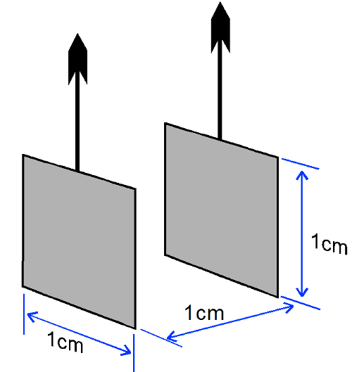
The relationship can be expressed as : Conductivity = Conductance x K factor.
K factor can vary from 0.01 to 100. Most commonly available probes are between 0.1 and 10. They are usually scaled in factors of 10 to make the job converting the conductance measured to conductivity reading easy.
Selecting the correct K factor for a particular installation maximises the accuracy of the measuring instrument.
Note that the constant for a given probe can vary from stated because of factors such as poor insulation, caking of solids on the electrode surface, gas bubbles, and erosion of the probe surfaces.
Effect of temperature on Conductivity Measurement
As stated in the introduction, measuring conductivity is useful because it is a good indicator of the concentration of ions in a solution. Unfortunately the conductivity of an aqueous solution varies with temperature so large errors may occur.
Temperature variation of the conductivity of a solution can typically vary from 0 to 5%/°C depending on what chemicals are in the solution and their proportion. Many substances the conductivity vary almost linearly with temperature. Neutral salts are typically 2%/°C so a 25°C change in temperature will result in a 50% change in conductivity reading.
Clearly some form of temperature compensation must be used for most applications if the conductivity reading is to be of any use.
Temperature compensation can be done in a number of ways. One is to draw off a sample of solution and maintain it at a fixed temperature to measure the conductivity. The more common practice with modern process instrumentation is to measure the solution temperature and to automatically scale the reading. This is all done internally within the instrument. The temperature compensated conductivity probe usually has a temperature sensor such as a thermistor built in. For accurate temperature compensation the instrument user must fully specify the temperature characteristic of the solution. The more practical method is to set the instrument to compensate at 2%/°C .
Conductivity Liquid Level Measurement
Used for the control or alarm of the level of conductive liquids. The tip of a sensing electrode is placed at the level which the liquid is the be controlled. When the level of the liquid touches it, an electrical circuit is completed through the liquid to earth - the current that flows is used to trigger a relay.
Almost exclusively used for liquid level control the point probe that requires a portion of the tank to be conductive.
Long two prong probes can be used from the top on insulated tanks. Additional probes can be used for measuring more levels.

pH/REDOX
Select products that can be used with pH and ORP probes. The term pH means a measure of the activity of hydrogen ions (H+) in a solution. It is therefore, a measure of the degree of acidity or alkalinity of an aqueous solution.
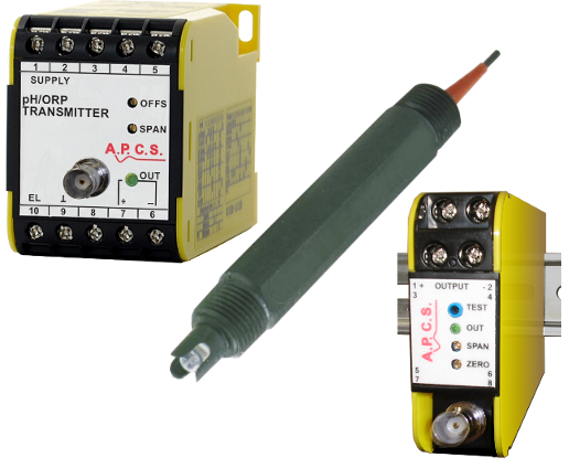
Water Chemistry Products
Acidity or Alkalinity
The acidity or alkalinity of a solution is determined by the relative quantities of Hydrogen (H+) and Hydroxyl (OH-) ions it contains.
A neutral condition pH = 7 is produced by an equal amount of (H+) and (OH-) ions.
An increase of (H+) ions will increase acidity while an increase of (OH-) ions will increase alkalinity.

Acidity or Alkalinity
Effect of Temperature
The degree to which water ionises to form (H+) ions varies with temperature so that the pH reading always returns to the same value at some given temperature. However, weak acids, bases and some salts ionise only partially in solution. The amount of ionisation is temperature dependant. If these ions affect pH, this will cause a pH change with temperature.
ORP (Oxygen Reduction Potential)
Oxidising or reducing properties of a chemical reaction. In this application, the term oxidation is used in its electrochemical sense and applies to any material which loses electrons in a chemical reaction. By definition, a reduction is the opposite of oxidation, or the gaining of external electrons. There can be no oxidation without an attending reduction.
For example, a ferrous ion may lose an electron and become a ferric ion (gaining increased positive charge) if a reduction, say, of stannic to stannous ions (which is the reverse of this operation) occurs at the same time.
This measurement uses electrodes similar to those in pH measurement (except that metal is used instead of glass), but the two types of measurement should not be confused. The measurement depends on the oxidising and reducing chemical properties of reactants (not necessarily oxygen). The inert metal electrode versus the reference electrode will produce a voltage that is related to the ratio of oxidised to reduced ions in solution.
This measurement is similar to that of pH in the requirements that it places on the voltmeter used with it. It is useful for determinations in waste treatment, bleach production, pulp and paper bleaching, and others.
Measurement methods
Measuring pH in an industrial situation is useful because it is a good indicator of the concentration of ions in a solution.
The pH measurement head is designed to house all combinations of Electrodes together with auxiliaries in the measurement Electrode, Reference Electrode, Temperature Compensation and perhaps an Ultrasonic Cleaning Head.
There are three main types of heads;
- Total Immersion type can be totally or partially Immersed in the process and has the advantage of being cheap but is easily damaged.
- Flow type is a modification of immersion type, being completely enclosed but having an entry and exit port. There are some of this type filled with baffles to protect the glass electrodes from the flow through the load.
- In-Line type is housed between two flanges and is essentially a piece of stainless steel pipe into which the measurement reference and temperature electrodes are fitted. Pipe diameters of up to 2" (50mm) can be accommodated with this type of In-Line unit.
Amplifiers (Signal conditioners) connecting to these probes should have an input impedance of 100M? or better to prevent loading and early ageing of the electrode.
Position
Select products that designed to accept signals from a slide wire, LVDT sensor or a resistance change.
For more information look under;
- LVDT
- Potentiometer
- Resistance.
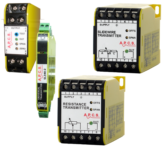
Position Products
The LVDT Sensor
An LVDT is an electromechanical transducer that produces an electrical output proportional to the displacement of a separate movable core.
The LVDT has many commendable features that make it useful for a wide variety of applications.
Friction-less Measurement, there is no Physical contact between the movable core and coil structure, which means that the LVDT is a friction-less device. This permits its use in critical measurements that can tolerate the addition of the low-mass core, but cannot tolerate friction loading.
Infinite Resolution, the inductor principle by which the LVDT functions gives a truly infinite resolution. This means that the LVDT can respond to the most minute movement of the core and produce an output.
Null Repeatability, The null position of an LVDT is extremely stable and repeatable. Thus the LVDT can be used as an excellent null position indicator in high-gain closed-loop control systems. It is also useful in ratio systems where the resultant output is proportional to two independent variables at null.
Cross-Axis Rejection, An LVDT is sensitive to axial core motion and relatively insensitive to radial core motion. This means the LVDT can be used in applications where the core does not move in a straight line.
Core and Coil Separation, permits the isolation of media such as pressurised, corrosive, or caustic fluids from the coil assembly by a non-magnetic barrier interposed between the core and the inside of the coil. It also makes the hermetic sealing of the coil assembly possible and eliminates the need for a dynamic seal on the moving member.
Environmental Compatibility, An LVDT is one of the few transducers that can operate in a variety of hostile environments. For example, a sealed LVDT is constructed of materials such as stainless steel that can be exposed to corrosive liquids or vapours.
How The LVDT Works
The LVDT consists of a primary coil and two secondary coils symmetrically spaced on a cylindrical form.
A free-moving, rod shaped magnetic core inside the coil assembly provides a path for the magnetic flux linking the coils.
When the primary coil is energised by an external AC source, voltages are induced in the two secondary coils. These are connected series opposing so the two voltages are of opposite polarity. Therefore, the net output of the transducer is the difference between these voltages, which is zero when the core is at the centre or null position.
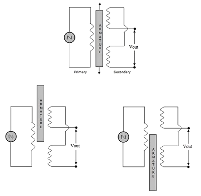
LVDT Operation
When the core is moved from the null position, the induced voltage in the coil toward which the core is moved increases, while the induced voltage in the opposite coil decreases. This action produces a differential voltage output that varies linearly with changes in core position. The phase of this output voltage changes abruptly by 180° as the core is moved from one side of null to the other.
Potentiometer / Slide Wire
A potentiometer or slide wire used to determine displacement or position. This could be a control on an operators panel or part of a closed loop system.
A reference voltage is applied across the slidewire/pot and then a sliding contact is used to pick up the voltage at various positions along the resistance element.
Typical Applications include;
- Actuator feed-back.
- Loading station for manual adjustment of process signal.
- Fixed output current source.
- Signal generator for system check.
- Resistance-change level devices.
- Slidewire position transducers.
- Slidewire pressure gauge.
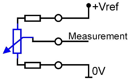
Potentiometer / Slide Wire
Potentiometer Input (Pot)
Pot input usually have zero and span adjustments that cover 20% of full scale.
The reference voltage generated by the transmitter will have a minimum pot value specified.
Slidewire Input
Modules with a Slidewire input have a non-interacting offset up to 100% of slidewire range enabling use on applications with sectional slidewires. Minimum span is 20% of slidewire value.
Slidewire Calibration Example
- 1000 Ohm slidewire.
- 4mA output at 500 Ohm.
- 20mA output at 750 Ohm.
Offset in this case is 50% (of 1k Ohm). Span is 250 Ohm = 25% of range.
Pressure
Select products with built in Solid state pressure sensors and produce a standard process signal output or alarm.
Pressure is defined as the force divided by the area, so that the force is the pressure times the area.
A given force can result from a large pressure over a small area or a small pressure over a large area even a small pressure exerted over a large area exerts a large force.
The SI unit for pressure is Pascal's (Pa).
Other common units include kPa, Bar, psi, Atm, mmHg, mWG.
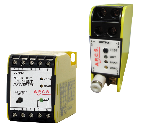
Pressure Products
Principle
Pressure may be expressed as a Gauge, Absolute, Negative gauge or Vacuum reading.
Absolute pressure is pressure measured with reference to a total vacuum i.e. absolute zero. Gauge pressure is a pressure measured with reference to atmospheric pressure where atmospheric pressure is the pressure above zero absolute that the column of substance above causes
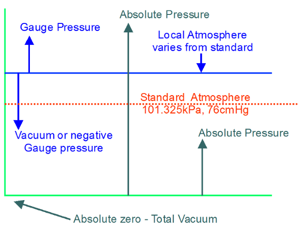
Pressure
Measurement methods
Because of the large amount of applications, a wide range of different pressure measurement techniques are available to the instrument engineer. Included are a range of mechanical measurement techniques incorporating similar principles and the popular advancing electromechanical techniques.
The physical principle incorporated in the design of a pressure transducer depends mainly on the range of pressures to be measured. The majority of pressure transducers consist of a force summing device which converts pressure to displacement or force, and an electrical element (e.g. resistive, capacitive, inductive, piezoelectric) which respond to displacement or force with an electrical output.
Solid state pressure sensors typically consist of a piezoresistive strain gauge in a Wheatstone bridge configuration which is integrally formed on a diaphragm (typically silicon). The application of a constant current source to the sensor produces a voltage output that is linearly proportional to the input pressure or strain on the piezo-resistive bridge network.
The Bourdon Tube in its simplest form and consists of a tube of oval section bent in a circular arc. One end is sealed and attached through a link to a pointer, the other end is fixed with an opening to accept pressure. When pressure is applied the tube tends to return to its circular profile and straighten out. The change in profile is transferred to the pointer which indicates a proportional pressure reading.
Resistance
Resistance is a measure of electrical conductivity. Its units of measurement is the OHM (Ω).
When a voltage V is connected to a load resistor R a current I will flow according to OHM's law;
R = V ÷ I
Example Resistance Transmitter Ordering Detail
- Input: 3-wire connection
- Cal: 10-50 ohms
- Output: 4-20mA.
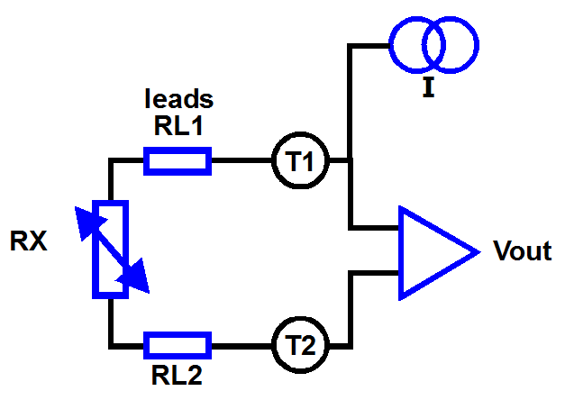
2-Wire Resistance Measurement
In this mode the resistance of the connection leads to the sensor is also measured.
Vout = I × (RL1 + RX + RL2)
∴ (RL1 + RX + RL2) = Vout ÷ I
This will influence the accuracy of the measurement for low values of resistance and may require on site calibration.
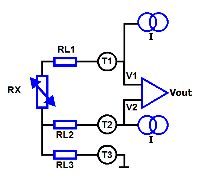
3-Wire Resistance Measurement
In this mode the resistance of one of the connection leads to the sensor is also measured.
V1 = I×RL1 + I×RX + 2×I×RL3
V2 = I×RL2 + I × RX + 2×I×RL3
Vout = V1 - V2I = I×RX (if RL1=RL2)
∴ RX = Vout ÷ I
If the leads are of the same length and type (RL1=RL2) then the errors due to leads are cancelled.
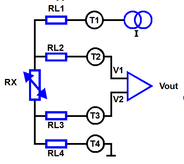
4-Wire Resistance Measurement
In this mode the voltage drop across the resistor is measured directly and the resistance of the connection leads causes no error.
V1 = I×RX + 2×I×RL4
V2 = I×RL4 Vout = V1 - V2I = I×RX
∴ RX = Vout ÷ I
Speed/Frequency
Select products that designed to accept pulses and produce a standard process signal or an alarm or a re-powered isolated pulse output.
Pulses from a sensing probe can define from
- magnetic sensors with a sine wave output
- flow metes this a square wave output
- proximity sensors with a square wave output.
The signal conditioning module may supply power for the sensing probe to operate. Engineering outputs representing flow, velocity and speed may be derived from a pulse input.
Important parameters to consider when ordering pulse input signal conditioners are pulse amplitude and frequency.
Strain Gauge
A load cell is a device for converting mechanical force into a proportional electrical signal. The applied force usually being gravity. Modern load cells use several techniques to convert the mechanical force into an electrical signal but typically connections are in the form of a Wheatstone bridge configuration.
Weight (W) is the force generated by a mass when an acceleration is acted on it. This acceleration is typically gravity but it can be any acceleration acting on the mass.
W = F = m × a. Where:
F is the force (N)
m is the mass of the object
a is the acceleration acting on the mass, typically gravity
There are many traditional applications for load cells, such as weigh bridges, but they have a wide application in almost every factory as a measuring and controlling device.
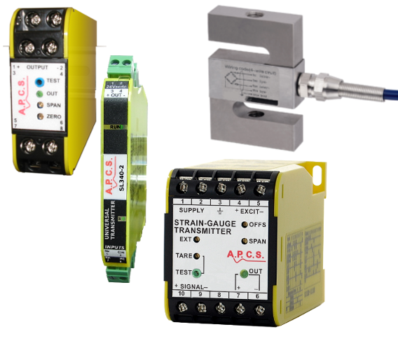
Strain Gauge Products
Strain Gauge Selection
A Load Cell will be specified with the following parameters;
- Capacity or maximum load that can be applied.
- Sensitivity typically specified in mV/V (millivolts output / Excitation Applied) at maximum load.
- Recommended or maximum Excitation voltage to be applied.
Using the equation Range = (Actual Load ÷ Capacity) × Sensitivity × Excitation
When connecting to a transmitter the Range, Excitation and Tare must be set.
If a Load cell of 1000kg capacity, with 2mV/V sensitivity is connected with 10Vdc excitation and the Actual Load is 500kg max. then:
- Range = (500kg ÷ 1000kg) × 2mV × 10 = 10mV
If the same 1000 kg load cell has a 100kg tare (tare = empty tank for example), with a 800 kg live load then:
- Range = (800kg ÷ 1000kg) × 2mV × 10 = 16mV
- Tare = (100kg ÷ 1000kg) × 2mV × 10 = 2mV
The Tare adjustment is the cancelling out of the load effect of the material holding container or vessel. An example would be the common metal tray used in grocery shopping, its influence (weight) is removed before the weight of the groceries is taken.